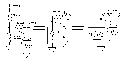
Norton's Theorem is a yet another way to represent the Thevenin black box
Instead of a battery, and a series resistor, inside the black box, the
Norton equivalent's black box, is a resistor, parallel connected to an ideal
current source. The resistor is exactly the same as that calculated in
the Thevenin world, and the Norton current source's value, is the Thevenin
voltage divided by the Thevenin resistance.
If you were to have a Thevenin Black Box, and a Norton Black Box, sitting
by side, making measurements on them would give you no clue to what's
inside. They both function identically from an electrical point of view.
Confusing Electrical Units:
E = Electromotive Force, measured in Volts
Note: The Volt is defined in terms of Current, and Resistance.
This seems like a circular reference, but that's the way it's done, such is
the art of this technology
One Volt = the voltage that results from one Ampere, flowing through one Ohm
I = Intensity of electrical current flow, measured in Amperes
one Ampere = one Coulomb per second
R = Electrical Resistance, measured in Ohms
G = Electrical Conductivity, measured in Mhos
Note: Ohms and Mhos are reciprocals of each other, that is, to convert
from one to the other you say...
Ohms = 1 / Mhos
or...
Mhos = 1 / Ohms
P = Power, measured in Watts
one Watt = one Joule per second
one Watt = the Power received by drawing one Ampere from a one Volt source
one Watt of heat applied to a penny dissipating in free air will be hot to
the touch, but won't boil water
Q = Quantity of charge, measured in Coulombs
One Coulomb = 6.2414*10^18 electrons
Yes Virginia they once used the kings foot, as a reference standard
I excerpt below, a small portion of the page that shows the US effort in the
area of trying to quantify, and standardize what exactly a Volt, Ohm, and
Ampere are
The Volt:
The portable Josephson Voltage Standard, a new compact, fully
automated calibration system for DC reference standards and digital
voltmeters, was developed over the past three years by Sandia in
cooperation with the National Institute of Standards and Technology
(NIST) in Boulder, Colo. Sandian Stuart Kupferman provided consulting
and acted as a customer interface during development of the portable
voltage standard, and Sandia's Primary Standards Laboratory
The Ohm:
Maintenance of the U.S. legal ohm requires research and the pursuit of
scientific breakthroughs in quantum metrology to maintain a local
representation of the unit, and requires close collaboration with
other National Metrology Institutes, including participation in
international metrology comparisons to ensure international
consistency of electrical measurements.
The Single Electron passing a point:
And by extension, 6.24 billion billion of them per second is an Ampere:
Researchers at the Commerce Department's National Institute of
Standards and Technology will announce in tomorrow's issue of Science
magazine that they have developed the first working prototype of a new
standard for measuring the storage of electrical energy-known as
capacitance-based on a means of manipulating and counting electrons
one at a time. The new system should be much simpler to use and faster
than the present technology used to set a recognized standard for
capacitance
The following phrase is a memory gimmick to help you remember Ohms Law.
The Eagle flies over the Indian, and the Rabbit.
Drawn graphically it can be represented as follows:
    Eagle                E
-------------  ====> ---------
Indian Rabbit          I   R
Cover the unknown, with your finger, and what remains in the Graphic, is
the formula to solve for that unknown. Example: to solve for Voltage,
cover up E, (Electromotive force, eg. Voltage) what remains of the Graphic
is IxR, or for another example, to solve for Amperes, cover up I,
(Intensity of current flow, eg. Amperage) what remains of the Graphic
is E/R
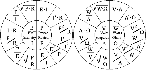
I show the twelve equation pie chart here, in your "scoopable notes" section
to make integrating this info into your studies easier.
I first need to mention that every one of these equations, is derived from
two relationships. The first is Ohms Law, which states that current flowing
through a circuit is proportional to the voltage applied to the resistor,
and inversely proportional to the resistance of the resistor. The second
relationship is that Power is the product of voltage, and amperage.
The equations from the Twelve Equation Pie Chart (center pictorial frame above)
are listed below, use your mouse to scoop these into your notes, they are
very handy.
E = I x R             V = A x Ohms

     P                     W
E = ---               V = ---
     I                     A
      ______                _________
E = \/ P x R          V = \/ W x Ohms


P = E x I             W = V x A

P = I^2 x R           W = A^2 x Ohms

     E^2                   V^2
P = -----             W = ------
      R                    Ohms


     E                      V
I = ---               A = ------
     R                     Ohms

     P                     W
I = ---               A = ---
     E                     V
       ____                  _______
      / P                   /  W
I =  / ---            A =  / ------
   \/   R                \/   Ohms


     E                     V
R = ---            Ohms = ---
     I                     A

     E^2                   V^2
R = -----          Ohms = -----
      P                     W

      P                     W
R = -----          Ohms = -----
     I^2                   A^2
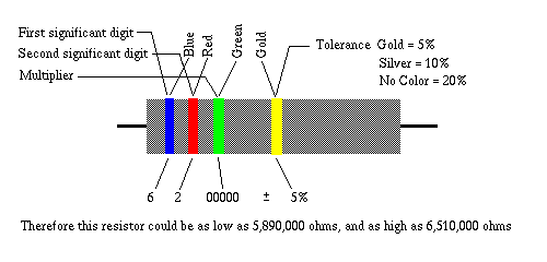
The following phrase is a method to easily memorize the Color Code.
"Bad boys rape our young girls, but violet gives willingly."
Starting at Zero, the first letter of each word in the phrase, corresponds
to the first letter of each of the of the Color names, hence, Bad equates
to the color Black, boys to Brown, rape to Red, our to Orange, and so on.
A perhaps, newer, certainly more politically correct version of the phrase
is given below, the same rules apply.
"Bad Boys Run Over Yellow Gardenias Behind Victory Garden Walls."
There are probably many more such phrases, to aid memorization of the
Resistor Color Code, and there are other Color Codes for other disciplines
and they have their own memory phrase gimmicks.
I show below the entire code...
Black    = 0
Brown    = 1
Red      = 2
Orange   = 3
Yellow   = 4
Green    = 5
Blue     = 6
Violet   = 7
Grey     = 8
White    = 9

Gold     = +/- 5%
Silver   = +/- 10%
No Color = +/- 20%
A resistor can only be certain ohmic values, the spacing
between seems to be roughly logarithmic, I list a table
of these below. If you suffer from Color Perception
Deficiency, a condition that is in part heredity, and
more often affects men, memorizing these values, or
atleast, printing a chart, containing all of these values
may help quite a bit.
Standard mantissa values for 5 and 10 percent resistors.
Values in parentheses are only available in 5 percent.
1.0   (1.1)   1.2   (1.3)   1.5   (1.6)   1.8   (2.0)
2.2   (2.4)   2.7   (3.0)   3.3   (3.6)   3.9   (4.3)
4.7   (5.1)   5.6   (6.2)   6.8   (7.5)   8.2   (9.1)

Standard mantissa values for 1 percent resistors.
1.00  1.21  1.47  1.78  2.15  2.61  3.16  3.83  4.64  5.62  6.81  8.25
1.02  1.24  1.50  1.82  2.21  2.67  3.24  3.92  4.75  5.76  6.98  8.45
1.05  1.27  1.54  1.87  2.26  2.74  3.32  4.02  4.87  5.90  7.15  8.66
1.07  1.30  1.58  1.91  2.32  2.80  3.40  4.12  4.99  6.04  7.32  8.87
1.10  1.33  1.62  1.96  2.37  2.87  3.48  4.22  5.11  6.19  7.50  9.09
1.13  1.37  1.65  2.00  2.43  2.94  3.57  4.32  5.23  6.34  7.68  9.31
1.15  1.40  1.69  2.05  2.49  3.01  3.65  4.42  5.36  6.49  7.87  9.53
1.18  1.43  1.74  2.10  2.55  3.09  3.74  4.53  5.49  6.65  8.06  9.76
The rules for reading 1% resistors are similar to
those of 5%, and 10% resistors, except that 1%
resistors, have three significant digits, not two,
followed by, in this case, the fourth band, that is
the multiplier. Since identifying the tolerance
percentage is not necessary in a system that is
exclusively intended for 1% devices, it is dispensed
with. On some resistors there is an additional fifth
colored band. It is a "Reliability Coefficient"
designator. It is often somewhat wider, and spaced
apart a little from the other colored bands.
Brown  = One in     100 drift beyond 1% in 1000 hours
Red    = One in   1,000 drift beyond 1% in 1000 hours
Orange = One in  10,000 drift beyond 1% in 1000 hours
Yellow = One in 100,000 drift beyond 1% in 1000 hours
Incidentally I have seen this "Reliability Coefficient"
on five, and ten, percent resistors, as well.
Here's a Lab assignment
Take some of those resistors you measured with your Multimeter, and try
reading their color bands, and see how closely your measured resistance
parallels the resistance you obtain by reading the color bands. If your
readings do not agree, calculate using the tolerance code, the minimum, and
maximum allowable resistance the resistor is suppose to have, and then,
give your eye ball reading of the Multimeter scale, the benefit of the
doubt, and see if after allowing for these errors your readings overlap.
Try your hand at calculating the wattage dissipated by resistors in previous
circuits. Hint: A 9 volt Wall wart powering a 160 Ohm resistor will dissipate
1/2 Watt. Obtain a 1/2 Watt 160 Ohm resistor (note 180 Ohm is close enough)
and connect it to your 9 Volt Wall wart, it should be warm enough to feel
the heat by touching the Body of the Resistor, within ten to 30 seconds from
the moment power was applied. Safety Note: Place your finger on the body of
the resistor immediately upon power up, don't wait for the device to heat up
first, this could avoid the nasty surprise, of touching an already hot
resistor.