Thevenin's Theorem is a technique to simplify a complex circuit that defies
ordinary calculation techniques, such that simple ohms law may be applied.
The first step is to identify the cause of complexity, and remove that item
from the circuit. If it's removal allows you to calculate voltages and
currents using ohms law, you have a Thevenizable circuit. Your task is now to
make simple equivalent circuits out of the rest of the surrounding circuitry.
Next re-insert the component you removed from the original circuit into the
simplified equivalent Thevenized building blocks, this should, if you chose
wisely, result in a simple series circuit that lends it's self to calculation
by ohms law.
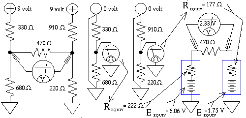
The technique of Thevenizing the individual portions of the remaining, now
separate circuits, is, on a case by case basis, calculate the open terminal
voltage, eg. the voltage that would appear if the component that causes the
complexity is removed, and write that voltage down. Then short the power
supply involved with that group of resistors, that is, replace the power
supply with a wire, and calculate the Thevenin resistance, looking back into
the circuit, including your wire, where ever it goes. It helps to pretend
you're calculating what an Ohm Meter would be reading. Generally the act of
doing this results in additional parallel paths, via the "short" you
substituted for the power supply. Once you've done that, write down the
resistance associated with that portion of the circuit. This resistance, and
the associated voltage calculated in the previous step, makes your equivalent
circuit, the "Thevenin Black Box". It is a battery, whose voltage is exactly
the open terminal voltage calculated earlier, in series with the Thevenized
resistance you just obtained.
If there were more than one Black Box, do the rest of them, and finally insert
your "temporarily removed component" (in this case a resistor) into the now
simplified circuit composed of Black Boxes. Simple Ohms law should now be
applicable.
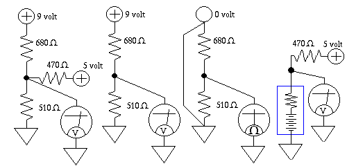
Here's a Lab assignment, construct the "Resistor Bridge" shown above, using
resistors of your choice, use values in a range of no more than a ratio of
5 to 1, try to predict the voltage across the center resistor, using
Thevenin's Therom, and in doing so remember your open circuit voltage.
Then construct your circuit, and make measurements, both with the resistor
connected, and without. Verify that your circuit, and your understanding of
it do what you expect them to.
Note: It is possible to wind up with zero volts across the center resistor
if that happens the exercise will be rather pointless, so choose a different
resistor value in one of the other four.
Also: If you have acquired a 9 volt wallwart don't be surprised if it does not
actually produce 9 volts, many produce as much as 12 volts when not subjected
to any load, and then when a load is applied their voltage is "pulled" down
to become closer to the labeled rating of the wallwart
Incidentally the Black Box power supply for the top picture, is a battery
voltage of 3.857 volt, in series with an R-thev of 291.4 ohms, thus the
voltage measured at the junction of the 470 ohm, and the Black Box,
is 4.294 volts. Other info, the drop across the 470 ohm resistor
is 0.7055 volts.
Back to Learn Electronics Next