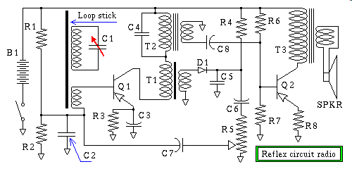
Click the "Audio discussion" link now, then
read on while it's downloading. When it
arrives, come back here, to study the above
circuit, as I explain how it works
Click the "Audio discussion" link now, then
read on while it's downloading. When it
arrives, come back here, to study the above
circuit, as I explain how it works
Your Notes:
Here are some real world measurements of inductance, by way of placing a
known capacitance across an inductor of an unknown inductance, and locating
the frequency of resonance, by lightly tickling it, the coil, with an audio
generator, through a considerably large resistance, and varying the
frequency, while observing the voltage across the coil/capacitor parallel
combination I find the "sweet spot" that is, the frequency that results in
the highest amplitude AC voltage. This frequency is the resonant frequency.
I can then use the resonant frequency formula, algebraically re-arranged, to
solve for inductance, "L" to arrive at an experimentally determined value
for "L" the inductance of the coil.
If that were all I did the numbers would have little meaning to you. This
whole process is fraught with error, and I'm about to prepare you for
a real world example of how error prone these measurements can be.
In each of the following experiments I start with two carefully selected
capacitors of identical value, or at least as near as I can find to identical.
The first example I used two 1.5 uf Mylar 50 volt capacitors, and a 120 volt
to 24 volt 200 ma stepdown transformer for the coil. The 120 volt primary
winding is never used in this experiment, as I am using the transformer as
an inductor, only. The transformer's 24 volt secondary winding is used as an
unknown inductor, that we are trying to measure the inductance of, by way of
resonance.
Here's the method:
I first wire both capacitors and the inductor in parallel, I find the
resonant frequency, and write it, the freq, and the total capacitance down.
Next I disconnect one of the capacitors, and again find the resonant
frequency, this should be the square root of two, times the previous freq.,
but as you will see this is not a textbook case. I write down that freq.
Next I disconnect that capacitor, and reconnect the other one, and
re-measure the resonant frequency. They are different, but not by much.
They should be identical, but this is real world. Next I average the two
frequencies, that were obtained using the two single capacitors, and write
that number, and the capacitors value, down. Next I compute the inductance
for the High capacitance, eg. two parallel connected capacitors, and their
attendant resonant frequency, and write it down, Next I compute the
inductance for the Low capacitance, eg. singly connected capacitors, and
their attendant averaged resonant frequency, and write it down. The
inductances obtained this way, should be, but are not identical, remember
real world. Finally I compute the percentage of discrepancy of the two
values for inductance. This will, or should surprise you, the audio discussion
that follows explains some of the reasons why these numbers don't agree as
well as they should, and what you can do in your circuit designs to make
things more predictable.
-------------------------------------------
I re-state the pertinent formula here for
convenience:

To find Inductance: (L)

                    1
L  = -----------------------------
      /            \ 2
     |   2  Pi  Fr  |       C
      \            /

Where:
Fr = Resonant Frequency in Hertz
L  = Inductance in Henerys
C  = Capacitance in Farads
Pi = the ratio of the circumference to the
     diameter of a circle


Experiment #1: Ind = 120v / 24v Xfmr
Cap = 3.0 uf   Fr = 57.6 Hz   L = 2.5449 H
Cap = 1.5 uf   Fr = 90 Hz     L = 2.0847 H
                       Variance = 22%

Experiment #2: Ind = Massive homebrew coil
Cap = 4.4 uf   Fr = 837 Hz    L = 8.2174 mh
Cap = 2.2 uf   Fr = 1250 Hz   L = 7.3688 mh
                       Variance = 11.5%

Experiment #3: Ind = Pot-core-ferrite
Cap = 4.4 uf   Fr = 10858 Hz  L = 48.83  uh
Cap = 2.2 uf   Fr = 15500 Hz  L = 47.92  uh
                       Variance = 1.9%

-------------------------------------------
Due to the fact that even many of the good quality function generators are
controlled by an RC oscillator, that is controlled by a knob that you turn
with a pointer on a dial, all the reading error sources, such as parallax
error contribute to your measurement error. You do however have sitting on
your desk, a piece of electronics that can digitally compose audio
frequencies, to the most exacting tolerances used in the most expensive
digital electronic function generators available on the market, if your
computer has a working sound card. To make this a reality requires you to
go down to your local Radio Shack, or Surplus store, and buy a cable that
has the tail of an alligator, and the head of a Pin... (jack)
Sorry I just couldn't resist using such an inviting pun, but seriously
ask for a one eighth inch stereo Pin Jack to alligator clip cable set,
or some combination of cables and adaptors that will provide the following.
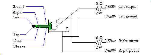
-------------------------------------------
To plug into the sound card, you want a
stereo 1/8" Pin Jack, and at the other end
you want four alligator clips, that are two
pair, of two each.

Pair One:  Left output
           Left ground


Pair Two: Right output
          Right ground

Do Not use a Monaural Pin Plug!  It will
short out the right channel driver of your
sound card, and probably damage it.

-------------------------------------------
www.programmersheaven.com/zone12/cat235/1166.htm
Linux Ncurses based function, and sweep generator
Description:
Make your linux box into a laboratory Signal Generator. Several Signal
Generator programs for generating accurate waveforms via /dev/dsp. Simple
command line and Ncurses based programs are included. Now has sweep signal
generators and a mixed tone/note generator. Also contains yet another mixer,
and a program to list some features of your sound support.
siggen:
Ncurses screen based Signal Generator for 2 separate channels. On stereo audio
cards the 2 channels are played on separate outputs. On mono cards
the 2 channels are digitally mixed onto the one output. Type of waveform,
frequency, amplitude, sample rate etc are specified/changed via a screen menu.
This is version 2.3 It plays continuously. Changes to parameters take effect
(nearly) immediately. This version is pretty CPU intensive.
sweepgen:
Ncurses screen based Sweep generator. It is like siggen. Changes to parameters
take effect (nearly) immediately.
-------------------------------------------
Title:     siggen
Version:   2.3

Keywords:  sound audio signal generation
           soundcard
Author:    Jim Jackson <jj@scs.leeds.ac.uk>
Maintained-by:
           Jim Jackson <jj@scs.leeds.ac.uk>
Primary-site:
ftp://ftp.scs.leeds.ac.uk/pub/linux/apps/

135K       siggen-2.3.tgz
6K         siggen.README

Platforms: Linux, requires soundcard and
           ncurses

Copying-policy: GPL

-------------------------------------------

ftp://ftp.comp.leeds.ac.uk/pub/linux/apps/siggen-2.3.tgz
Your computer is, or should be, connected to a grounded electrical outlet,
this poses a hazard to your soundcard if the circuit under test, is also
connected to a grounded piece of equipment such as a VTVM, (Vacuum Tube Volt
Meter), or more likely an Oscilloscope. The problem arises if you fail to take
into account that the output of the soundcard could be shorted, if it's live
signal carrying wire is connected to the ground side of the Oscilloscope's
input. The path of current traverses through the metal case of the
Oscilloscope, out the power cord, into the safety ground of the wall outlet
across the ground wiring of house, to the wall outlet powering the computer,
to the case of the computer through the computer's safety ground, and finally
to the soundcard signal ground. Trust me, it's a direct short, offering less
than one tenth of an ohm in extreme cases. I want you to do the experiments,
but I don't want you to blow up your computer. One way to prevent even
accidental shorts, is to place an eight ohm resistor in series with the clip
lead carrying the output signal from the sound card. That way, even if the
alligator clip were to accidentally slide off the table and touch a grounded
device, it would be no worse, of a load, than if you had plugged in the
speakers. This ofcourse offers no protection against an accident where you
somehow put power back into the poor soundcard, but then if you did that to
a thousand dollar function generator, you'd blow it up too.
Your Lab Experiment:
Find several large inductors, or use a winding of a transformer as an
inductor, and construct a resonant circuit using a non-polarized capacitor,
tickle the resonant circuit with the output of the soundcard fed through a
series resistor that is atleast a hundred times the ohmic value of
the DC resistance of the inductor, measured with your ohm meter (multimeter
set to RX1 scale), but no lower than the 8 ohm short protection resistance
mentioned earlier. Using the soundcard as a Function Generator, set the
waveform to Sine Wave, and run the frequency up and down, while measuring
the AC voltage across the coil. Because of limitations of the audio frequency
response of the sound card, avoid using frequencies below 30 hertz, or above
10,000 hertz, some sound cards are better than others, but they are after all
only intended to be audio devices. If you don't get a resonance peak, or if
you get one, but it is near one of the frequency extremes, eg. audio
spectrum limits, change the capacitor, to get the resonant frequency down or
up into a more measurable region. Now find the resonant frequency, and then
use the formula discussed earlier to compute the inductance of the coil.
If you are being careful, you should also be comparing the output voltage of
the soundcard, since it may vary in amplitude as you dial up or down the
frequency. To be a good measurement, you should control the soundcard's
output level so that it's output voltage remains constant, so that your
measurements are not affected by the audio roll off curve of the soundcard.
If your meter is not sensitive enough to adequately read the output of the
sound card there are some simple things you can do. You can amplify the
soundcard's output, this has the advantage, if you use an old stereo as the
amplifier, of providing you with a knob to set the gain of the amplifier,
and thus the amplitude of the signal, a much quicker operation, than gliding
the amplitude up or down via the keyboard. You just grab hold of the knob,
and twist. A less expensive solution is to use a stepdown transformer, in
reverse. The low voltage produced by the soundcard, sent into the 6 volt
winding of a 120 volt to 6 volt stepdown transformer, produces at the
terminals of what is normally used as the 120 volt primary, an output of up
to 10 volts of audio. This does not come without it's drawbacks. First of
all placing a transformer in the signal path of a function generator is
probably only useful if the Function Generator is set to Sine Wave.
Square waves look laughably weird after they go through a transformer, and
triangle waves look more like distorted sine waves than what they're supposed
to be. Secondly the transformer being a reactive component further introduces
a frequency response curve of it's own, on top of the already undesirable
response curve of the soundcard itself. The following is a table of
frequencies versus voltages with and without a transformer, to boost the
voltage. In the fourth column I introduce a 330 ohm load resistor on two of
the highest voltages to give you a feel for the type of load such a soundcard,
transformer combination will bear.
-------+-----------+-----------+-----------
Freq.  | Snd Crd V |  w/trans  | trans+load
-------+-----------+-----------+-----------
   2Hz |    0.00 V |    .035 V |
   8Hz |    0.16 V |    .039 V |
  20Hz |    0.37 V |    0.55 V |
  80Hz |    6.64 V |    10.0 V |    3.57 V
 200Hz |   0.702 V |    8.63 V |    4.93 V
 800Hz |    6.84 V |     7.9 V |
2000Hz |    0.58 V |    7.32 V |
8000Hz |    0.10 V |     3.1 V |
-------+-----------+-----------+-----------
If the above has a chance of working, then the following proposal might
make this sort of thing vanish in a puff of logic, imagine Function Generator
software, that has to be trained by the end user. The training phase would
go something like measure the voltage at the output of what ever soundcard,
amplifier combination you will always use, this includes the tone, treble,
and bass knobs set to some easily repeatable position. The program asks you
to measure with a Peak-to-Peak reading digital meter, the output of the whole
setup, and key in the result at the prompt, then press enter, to go on to the
next reading. It does this some nice round number of times, like 256 times.
In case you are unfamiliar with binary, 256 is a nice round number.
After it is trained, and the lookup table is saved to a file, it then uses
that lookup table to correct for frequency response variations, of the
system as a whole. Given time I may explore this, if I ever get this Web
site done.
Limits of Soundcard, Function Generators:
In addition to all the previous foibles, I need to discuss the sampling rate.
If the sample rate of the soundcard is set to 32 kilo hertz, and you try
to approximate a sine wave of 4 khz your waveform only has 8 discreet steps.
That's only 2 steps up, 2 steps back down, 2 more steps farther down into
the negative range, and finally 2 more to return to the zero we started at.
That's an awfully bad approximation of a sine wave, on the other hand, if
you set the freq. to 400 hz you now have a sine wave approximated with
forty little stair steppies, pretty good really. So even though the Function
Generator can do the higher freqs, be aware that using them introduces
"Digita" into your "Analog" :-)
This is also a compound problem, as you go up in frequency, wave forms
generated by the software. in order to get the frequency right, have to
"roll in, and roll out" of the wave interval, the sample aliasing phenomenon
manifests itself as noise, since from one wave to the next, the point where
the software decides to slice the threshold for the stair step, is now not
in the same place as it was last wave, thus more "Digita" in your
"Analog" So why is it that we don't notice it when playing back audio?
The answer is profound, and simple, your ears deceive you, part of the
reason algorithms like MPEG work as well as they do, is in part due to a
whole field of science called Psycho-acoustic Research, that endeavors to
understand how best to deceive the human ear-brain combination, into
believing it is hearing what was in the original recording, and thus
allowing much less data to represent the sound, than would otherwise be
required
-------------------------------------------
I wrote an audio compression system of my
own design, you can find it in
http://www.zap-tek.com/files/asdf-0.4.tgz
-------------------------------------------
The experiment was performed with three 2.2uf caps in parallel, for a total
capacitance of 6.6uf, and then with only one of the caps connected to actually
get two different resonant frequencies. The inductor was a one-to-one ferrite
pulse transformer, wired up in series, so that primary, and secondary, add
to the inductance, for a total inductance, measured earlier by a different
method, of 1.64mh. I also used a 120-to-6volt stepdown transformer, in reverse
as described previously, to get usable voltages.
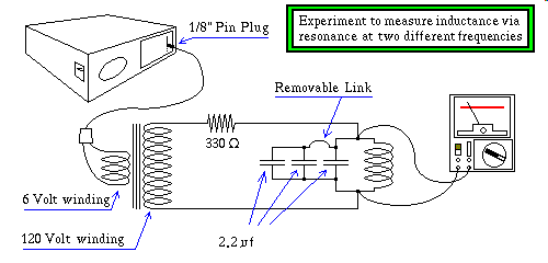
Here are the results of this experiment.
-------------------------------------------
Experiment #4: Ind = 1.64mh coil
Cap = 6.6 uf   Fr = 1591 Hz   L = 1.5354 mh
Cap = 2.2 uf   Fr = 2671 Hz   L = 1.6137 mh
                       Variance = 5.1%
-------------------------------------------
Remember my telling you, not to rush out and buy a digital multimeter, or
some fancy electronified autoranging analog multimeter? In preparation of
this lesson, I took the time to actually measure my own test instruments.
I actually have an assortment of these fancy things, and I use them once
in a great while, but they do lie to you.
My old standby, the Micronta 43 Range Doubled VOM, when properly terminated
with a 50 ohm resistor at the meter, and driven with a home brew Function
Generator, that is as good as any thousand dollar Wave Tek, this is not an
under statement, it is flat to 8 mhz, on all waveforms! The Micronta 43 Range
Doubled VOM, was within 8% of proper reading to 10 mhz, the two digital
multimeters both showed 0.000 at only 150 kc, and at 14 kc they displayed
the 35% 20% of the proper input voltage, even worse the one that read 35%
would read different voltages upon changing the range switch on the meter
itself, the 35% dropped to 14% when you selected the next range decade.
Lastly the accuracy of the electronic autoranging analog multimeter, fell
apart so bad at 5 kc, that it was unusable for this experiment. The one
electronic meter that did work well, was a Heathkit Field Effect Transistor
equivalent to the old industry standby the Vacuum Tube Voltmeter. These are
fundamentally different in design, they do not place amplifiers in the AC
path of the signal, instead to read AC, they build a back biased voltage
doubler to condition the incoming AC signal into a peak to peak DC
representation of it, before any amplification is performed. This nearly
eliminates the frequency response problem, but introduces the draw back
that, what you, the end user; are reading is peak to peak AC voltage, and
therefore you must know something about the waveform you are reading, and
make calculations on the results read from such a meter. Radio Shack, and
others sell what they claim are Fet based meters, It's not so much the Fet
circuit that makes such a meter special, it's the fact that AC signals are
not what's being amplified, and you need to look at the circuit digram to
tell for sure, whither it's a keeper, or not.
In the above drawing, the transformer is doing more than simply stepping up
the voltage of the sound card. Because there is no electrical connection
between the circuit under test, the "caps, inductor, 330 ohm resistor, and
the Micronta multimeter" -and- the
"computer, with soundcard", you nolonger have to worry about ground loop
problems. This aspect of transformers, is
called " isolation " Just as a lone
flashlight battery sitting on a wooden shelf could power a lamp, assuming
both ends of the battery are connected to a lamp by wires, this circuit is
at present not ground referenced, it is said to
be " floating " or
isolated from any other circuit. They make isolation power transformers,
that have a 120 volt plug on one end, weigh about ten pounds, and have built
into one of their end bells an electrical wall socket. These tend to provide
large amounts of power, the smaller ones producing half a kilowatt, and they
tend to be rather pricey, because of their size, and the amount of materials
required to build them. So why would you want a device that takes in
120 volts and outputs 120 volts, it doesn't seem at first brush
to be very useful. One big reason is safety. When working with voltages as
high as 120 volts, isolating the secondary means that if you should
accidentally come in contact with only one wire of the isolated secondary,
assuming that anything it is powering, hasn't, inadvertently re-established
an electrical ground, there is no path for current to get back to you,
isolation prevents a complete circuit. Never Ever Rely on this! Yes it
could save your life, but coming to rely on it, can get you killed as well.
If you have one of these, a good thing to do, is to plug it into the wall
outlet, and plug your Variac into the isolation transformer. Your Variac now
allows you to dial up any AC voltage from zero to 150 volts or so, and not
have to worry about ground reference, as you connect up a circuit, and make
measurements with some electrically grounded piece of test equipment, like
an Oscilloscope, perhaps, your computer's soundcard while running
the Xoscope program
but heed my warning, as soon as you connect your grounded test equipment to
the circuit, the special property the Variac inherits from the isolation
transformer, is now nolonger present, and wiring in portions of your circuit
are electrically "hot", meaning that if you should accidentally touch them,
they can give a lethal shock, through the ground path, via the computer's
safety ground! The advantage here is that the if not for the isolation
transformer, attempting such a measurement could blow up your computer,
passing tens of amperes through the delicate circuit foils of your
motherboard! Also, though it is rare, there exists a failure mode, in which
the two isolated windings can short to one another, inside the isolation
transformer itself, rendering it unsafe, or perhaps not reliably isolated.
If it blows up your computer, you will be unhappy, if you mistakenly relied
on it for electrical safety, you might end up dead, and dead is a
significantly more difficult kind of thing to deal with.
Safety:
I intend to flush out this part with numerous Web Resources, at some later
point in the sites development, but I want to give you a few real life
examples of how to kill your self, I'm still alive, but it is only by luck.
Accidents happen in the most unpredictable of ways, at a very young age,
10 years old if memory serves me right, I had a firm understanding of
electrical safety, and the notion of ground paths was firmly under stood,
as well as what currents could be expected to flow through various
conductors and insulators, and things in between. While on a rooftop one
dry summer day, I reasoned that touching, and subsequentially using the
power line coming to the house to balance myself, should be harmless
even though the line was known to be hot, because I knew the composition of
the material I was standing on was orders of magnitude higher than what was
required for electrical safety, hence as long as I did not complete the
circuit, it would be safe to use the taught live wire, carrying 120 volts
to stabilize my balance to reach something caught on the wire, a kite string
I think. The reasoning was solid, as far as it went. I was indeed safely
able to do this. Unfortunately, I started to loose my balance, and
instinctively reached out for anything to grab hold of. The drain gutter,
was well within reach, it was also quite well grounded. This placed me
with one hand on the live wire, and the other on the electrically grounded
drain gutter. The shock was so severe that as I lost consciousness I relaxed
the grip, on both the wire, and drain, and fell twenty or so feet to the
ground below, breaking the circuit in the process. Had I not been dangling
my body weight I may very well have died. Four years later while working on
a 700 volt powersupply, that was turned off, but still had a charge on the
rather large filter caps, I reached in with a pair of ordinary pliers, to
short out, and discharge the main capacitor bank. The chassis was sitting
on wood, it was completely disconnected from the power mains, thus no ground.
Touching the hot side of the capacitor bank, in theory should have been
safe, however, as I did so, the whole powersupply started to fall toward me
so I reached out with the other hand to brace it to prevent it from falling
to the floor, this completed the circuit, and I did indeed discharge the
main capacitor bank, albeit through both of my arms. The muscle spasm that
resulted from a 700 volt jolt, pulled muscles so badly that they were sore
for weeks afterward. Then a year later, I was over at a friends house
repairing a large, TV set, we had identified the problem and warmed up the
soldering iron, I snipped out the bad component, and it fell down inside,
trying to reach down inside, and grab it, caused the whole TV set to shift
it's weight, and it started to fall off the bench, once again I instinctively
grabbed the top edge of the wooden cabinet, to stop it's fall. Once again
unfortunately, the soldering iron, now good and hot, was also sitting on the
top edge of the same wooden cabinet, I heard the searing sound of meat,
and the pain, and second degree burn, was not one of the happier things I've
encountered in life. I have learned an unusual response to things falling,
jump away, let it fall, the damage that often happens to you, by following
your instincts, is much more long lasting, and severe, than the cost of
replacement, should the item break. I'm not going to mention names, but
those who read this page know who they are, one in particular, was soldering
a fairly large metal mass, about the size of a silver dollar, when it started
to fall, instinctively he grabbed it, Yeeeow, and dropped it, it bounced on
the bench, and then headed for the floor, he instinctively grabbed it the
second time, Yeeeow again, two burns for the price of one. Instinct is, to
borrow a phrase from Dune the movie, the mind killer, and it will kill you
if you're not careful. Something that should be obvious, but many a dead man
missed it, your heart is nearly centered between your two arms, which makes
the most likely path of current in an electrical accident, even more lethal.
Voltage isn't what gets ya' as little as a nine volt transistor radio battery
killed someone who tempted fate one day, by sticking pins into his finger
tips and touching them to the terminals of that innocent looking battery.
Measured from your toe to your head, with a subcutaneous electrode the
average human body offers only 600 ohms of electrical resistance, fifty
milliamperes can be lethal, the shorter path through the arms, and a person
sensitive to heart rhythm abnormalities, and a little imagination, and it's
not difficult to see this happening. So why are so many people lucky? Set
your ohm meter to the highest resistance range possible, probably the "R"
times 10,000 scale setting, and touch both meter probes to two fingers of
the same hand, first dry, then moistened, under no circumstances place the
probes one in each hand, if the meter is working properly there should not
be anywhere near enough current for you to even feel, let alone be harmed by,
but what if your instrument were defective, you are trusting your life to
this experiment. The measurement you will see for a dry pair of fingers is
over a megohm, and even wet, they are in the tens of thousands of ohms.
So you say Ohms Law would dictate that I am an insulator, and a rather large
voltage is going to be required to hurt me. This is true most of the time.
However in an electrical shock muscles are stimulated by the current, they
cause you to grab more tightly than you ever would grab anything of your own
volition. If the electrode punctures your skin, the resistance drops to the
mere hundreds of ohms, which is often fatal. Electricity and it's attendant
ever present danger is never to be taken lightly, that's when it will get
you. On the other hand high voltages that cannot carry significant current,
although they may not be pleasant, are not lethal. A good example of this is
static electricity, thousands of volts are present, but I have never heard
of static killing anyone, they may wish they were dead, if what they touched
was a grounding discharge wire dangling from a helicopter, those generate
hundreds of thousands of volts, current is low, but I assure you it ain't fun.
Another kind of injury that can occur even at low currents, of high voltage
RF, can have long term, potentially lethal consequences. Here's what happens
you get your finger too close to an RF source, and a plasma arc jumps through
the air. The frequency is so high that a phenomenon known a skin effect,
alters the conductive characteristics of any conductor, including your body.
What happens is that the current flows around the outside of you, rather than
through you. There is ofcourse a downside to this, the point where the plasma
arc makes contact with you, is carrying a temperature of about 5000 degrees
Fahrenheit. As it starts to burn a hole in the tip of your finger, your
reaction is to pull away, unfortunately it has other plans. Once the air
atoms form plasma, they can bridge an arc about three times as long as the
length of arc they jumped to initiate it. This insures a cone shaped hole
in the end of your, now smoldering finger. Because of the temperatures involved
this smoldering tissue is perfectly sterile, cauterized. Your problems have
only begun, unlike medical devices, that do much the same thing, you weren't
properly prepped for surgery, standing there in your shop. This generally
gets badly infected, in a day or two, and depending on how virulent the
pathogen on your skin, and the surrounding area is, you could, conceivably
wind up in the hospital, waltzing the IV pole around the ward for months,
of slow antibiotic therapy. Failing to discharge a CRT's second anode, that's
the nasty 25000 volt TV Picture tube, before you work with it, is unlikely
to shock you to death, however when this happens to someone, unexpectedly
they tend to drop the Picture Tube, if it breaks, it will implode sending
glass shards in all directions, as the Tube Goes It's Separate Ways!
Can we say if you survive, you won't forget to do it the next time.