Please read the copyleft link at the bottom of this page for further details, the rights given by this license are very generous. Not at all like most licenses you are probably familiar with.
Now there I've gone an done it, gotten way off the path, so here goes, good luck, building a nice simple LED flashlight.

You are looking at an LED Flashlight, powered by a single "D" cell flashlight battery. There are several advantages to running on a single cell. One is the amount of stored energy, I list common battery sizes below, and their MaH (Milliamper Hour) rating, as well as their volume in Milliliters, as there is an interesting approximate correlation between Ampere Hours, and Volume.
Size   MaH   Volume/ML   AH/Ml
AAA   1250    3.899      0.321
AA    2850    7.429      0.384
C     8350   24.188      0.345
D    18000   49.226      0.366
With the brightness knob turned up to maximum, the unit draws about one amp. At 18 ampere hours a new alkaline "D" cell will last about 18 hours, at an out of pocket cost of one dollar US. given current pricing in 2010. From a brightness perspective this thing compares favorably to a two cell flashlight, owing to the efficiencies of the modern semiconductor devices used in the LED flashlight.
It's an unusual design to say the least, and it allows you to power many things, not just LEDs from a single cell. Rechargeable batteries never attain their advertised number of recharges if the batteries are wired up in series. The reason this is done of course is to get the voltage up to usable potentials. The problem with doing that is that sooner or later one of the cells in the battery, battery here being used in the technically correct usage of the word, meaning a voltaic pile of many cells, wired in series, anyway, the problem is that when you charge a battery of several series wired cells, sooner or later one of them will get ahead of the others, and then as if designed to make matters worse, over successive discharge, recharge cycles one cell slowly gallops ahead of the rest of the pack, eventually getting way out in the lead charge wise. This sort of thing is not good, the lone outperforming cell at some point begins to get overcharged during every charge cycle. Consider this, if this lone outperforming cell is dropping more than its fair share of charging voltage, what about the other cells? Well they end up getting less and less every recharge cycle that passes. It doesn't take very long before the entire battery of cells, fails to produce adequate energy stores on the discharge cycle. Result... Replacement! What if you were to replace the lone overcharged cell? That would, and does, bring the battery of cells back on line, for the duration of their rated life. So all of this begs the question, why not design for a single cell to begin with, where a charge monitoring computer can do a perfect job. This is particularly important in solar powered self recharging systems, stationed out in remote regions where it's costly to send a man out to swap the battery. Item: Since the 1960's GE NI-Cads were rated at 1000 discharge-recharge cycles, however they seldom realized this in series strings, but if you used their GE branded charger, which required you to remove them from your device, and using the certified charger which charged each cell separately, they achieved noticeably longer life.
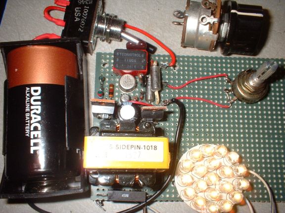
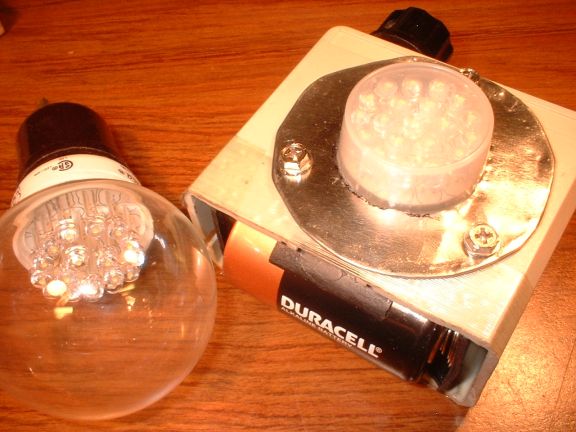
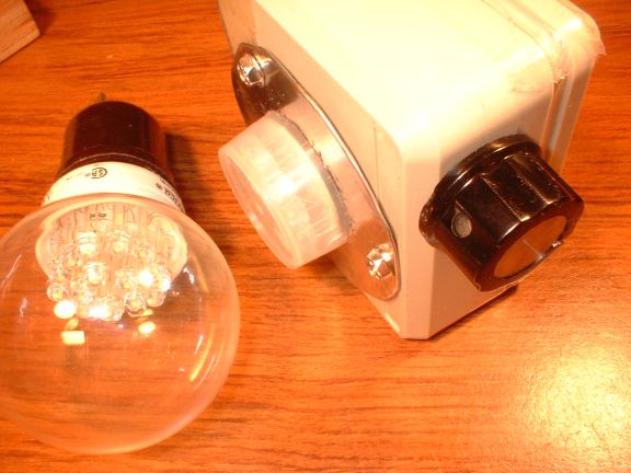
The disc with the 20 LEDs in the photo above, came from a Lights of America screw in LED replacement for an incandescent light bulb, shown in the photo below.
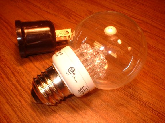
Obviously the Lights of America device sold at stores everywhere, is designed to operate at 120 volts AC, in fact the disc drops 52.5 volts, the whole thing works on the principle outlined in 014 Impedance Experiments If you click on that lesson, and then search for the phrase...
Contemplating the cosmic one-ness of the above experiment
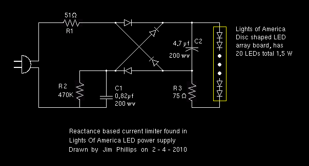
The two paragraphs that follow sum the experiment up nicely, pointing out that a pure reactance while drawing current, does not pull power out of a wall socket. The design of the Lights of America LED lamp uses this principle, and places a diode bridge rectifier between the LEDs, and the reactance current limited wall socket voltage. Yielding a nearly one hundred percent efficient power supply to drive the LEDs.
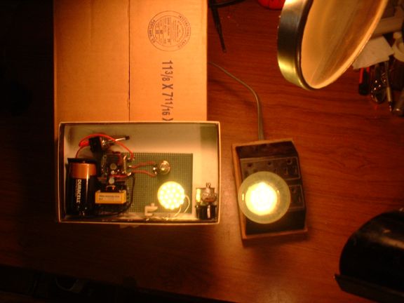
Using a Xenon flash can render deceptive results, but no flash at all will cause the light sources under test to saturate the camera's imager; even film, if you can remember back to those dark times, has a similar problem, called overexposure. In either case it makes, or rather it can make to different light sources that have very different brightness, appear to be equivalent. To avoid this sort of thing, I used a partial flash, some external lighting, and a side by side comparison in the above photo, to show that my Single Cell LED Flashlight, and the original Lights of America lamp are indeed close enough in brightness to calm such concerns.
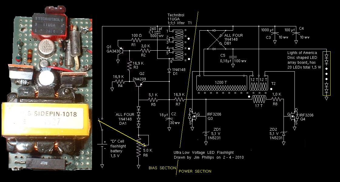
The following photo / schematic is followed by a preview scrolling window to allow you to keep the schematic in view and yet allow you to read ahead. Not all browsers recognize the type of data object that this scrolling window is, so I duplicate the same text for their benefit, if your browser promotes this feature, read the text in the scrolling window, while studying the schematic, and then simply skim down past the strange saturable reactors that were at the end of the scrolling windows data set, to finish viewing this project.
Some perspective:
This project will teach you things that you only learn by actually building something real. This device operates on as little as 0.76 volts. Since flashlight cells are specified to be at their End Of Life (EOL) at 0.9 volts no load, such a device will suck all the life out of its battery. Perhaps even more interesting, Power MOSFET (Metal Oxide Field Effect Transistors) require as much as 4.0 volts of Gate (input) voltage to even begin to turn the device on. So directly driving the gate of a MOSFET with even a brand spanking new 1.6 volt cell is not going to work. I solve this by building an ultra low voltage oscillator that has at it's heart a Germanium Transistor. There is nothing all that special about this germanium PNP transistor, it won't be subjected to collector current above 20 ma, or voltages above 6 or 7 volts, the whole thing runs on a single flashlight cell. As far as Ft goes an audio transistor would be just fine. Beta gain, well 15 would probably work, get the best you can, without spending extra for it, a Beta of 50 is fine, and 200 is ridiculous, though it would probably work even better. Basically the audio final power-amp in a six transistor radio is a common transistor, just make sure it's PNP germanium, you can test that by measuring the forward junction drop from the emitter to the base. This oscillator drives a transformer (multi-tap coil actually [T1]) that is half wave rectified [D1] and stored in a capacitor [C2] before providing bias through [R7] to the two MOSFETS [Q3] and [Q4]. The bias oscillator is very stable, owed to the fact that it just loves to oscillate, as little as 0.15 volts DC across the power supply rails will cause this oscillator to break into oscillation, hence the need for a Germanium transistor [Q1], but to get usable output from it requires 0.45 volts. or so. The MOSFETS I used begin turning on at a gate voltage of around 3.0 volts, which assuming a "D" cell voltage of at least 0.76 volts, enough for the oscillator formed by ([Q3],[Q4],[T2]) to oscillate powerfully enough to light all 20 series wired LEDs, albeit very dimly, while only drawing 7.6 milliamperes.
Back to the biasing network, oscillator ([Q1],[T1]) and the half wave rectifier [D1] not only biases the MOSFETS, but also feeds back through a silicon transistor [Q2] that when turned on starves-off the bias of [Q1] the bias oscillator, in effect turning it off a little bit. This action, and the forward biased regulator diodes [DA1] (diode array one) tempered by the variable resistor [R6] permit control of the MOSFET bias, and thereby the power output of the two MOSFET oscillator [Q3] [Q4] and [T2]
Note: The regulator diodes, [DA1] are NOT Zener diodes. The voltage is so low, that they regulate in forward biased mode.
Further note: Motorola makes, or at least did make at one time, a 250 mw series of zeners beginning with voltages at 1.8 volts for part number MZ4614, and 2.0 V for MZ4615, and 2.0 V for MZ4615, and so on up to 6.7 V for MZ4627. They skip 0.2 volts at a time up to 2.4 volts, then the iterator changes to 0.3 volts for the rest of the series, so you could do it with a single diode, however I didn't have any of those on hand, nor are they likely to be in any parted-out surplus junk you have sitting around.
Please reference the above schematic while reading this section, or you are likely to get confused. The effect of lengthening diode array DA1, that is to add an extra diode, is to add an extra half a volt to the bias oscillators DC output, the converse is also true, shorten it by one diode, and it runs a half a volt lower. I mention this in case the MOSFETS you find, have an unusually high, or low, gate threshold voltage. On a similar note, R5, and R6, have the same value. The significance here is that at low currents a Silicon junction drops 0.5 volts, this is true for the emitter base junction of Q2 and for each of the diodes in DA1. As designed they add up to 2.5 volts, and the voltage drop across R5 sets up a current that adds an additional zero-to-0.5 volts across the potentiometer R6, for a total bias output that is adjustable from 2.5 to 3.0 volts. I had this very nice switched potentiometer but it was 2.5k ohms. To make this circuit suitable for using this potentiometer, I changed R5 to 2.4k, as that was the closest value I could find to 2500 ohms, the value of the potentiometer I substituted the 5k ohm pot with.
The previous substitution is one of many possible substitutions, obviously there is a limit to how low, or for that matter how high, you can go before you begin to affect the performance of the bias regulator. Going lower you begin to draw ever more current from the oscillators signal coming out of T1 and D1 which then require more initial starting voltage from the "D" cell battery. Going the other direction you may actually improve on the initial starting voltage spec, only to end up making the regulator unstable. I list below a few guesstimates based on some experimental testing of the bias circuit.
Value of       "D" cell  voltage
R5 and R6      required  to  get
               bias   regulation

5.1 k ohm              0.91 Volt

2.4 k ohm              1.15 Volt

1738 ohm               1.31 Volt
The Power MOSFETS Q3 and Q4 are very special in one very important way, when they get a gate signal to turn on, they turn on very hard, the ones I selected came out of a modern design switching type UPS unit, one that first jacks the 12 volt gel cell battery up to about 170 volts RF, then rectifies it to DC, and then using a low frequency, 60 Hz switching bridge-amp, chops it up into a modified AC square wave that approximates a sine wave by resting at zero about half the time, and shooting up to a plus 170 volts then back to zero for a while, and down to a negative 170 volts for a while and finally back to zero to complete one cycle. The MOSFETS that were powered by a 12 volt DC source to drive the primary winding of the RF Ferrite transformer, were fused at 45 amperes. To do that efficiently they had to have a rather low on resistance and do they ever, they sport an rds-on resistance of a mere 8 milliohms! I know, I looked up the data sheet on the Internet. Sure you could buy them, but why, when they're so close at hand. As for things like gate to source voltage being exceeded, the mere handling of these devices can generate enough static electricity to permanently damage them, I wrapped bare wire wrap wire around all three pins while unsoldering them from the UPS circuit board, and then I soldered a 5.1 volt zener diode across the gate, and source leads before removing the wire wrap wire. A Vz (zener voltage) of 5.1 volts is not written in stone. Most power MOSFETS have gate to source of 10 volts or better, leaving lots of wiggle room for the selection of a zener diode. Nor would you want to go much lower than 5.1 volts as you are just a couple of volts away from starving off the gate voltage, preventing the MOSFET from completely turning on. The rest of the voltages, wattages and the like almost have to be within spec, after all we're operating this thing on a single flashlight battery. One thing I probably should mention though, the gate to drain capacitance inherent in the device is probably much larger than you would expect, how else do you think they get the tremendously low rds-on resistance? By making the FET in much the same way you make an integrated circuit, they wire thousands of the little buggers up in a three wire parallel circuit.
The large ferrite transformer needs some discussion. first of all there are essentially two types of what most folks think of as ferrites. It's one of those words that gets misused a lot. A true ferrite, the magnetic core, is actually a solid state material, though not manufactured to a purity anywhere near a solid state device such as a transistor, they are a large single metallic crystal. The other type of material frequently used in these types of coils and transformers is ceramic powered iron. I used to make transformers for a living, (note it's not that glamorous) still I learned a lot, one item in particular is the whole notion of what a magnetic gap is, or does. An AC transformer is made without any gap at all, yielding the smallest effective AC transformer possible, add even a small gap, and the Core material requirement goes up alarmingly, and with a larger core, you also need longer, fatter wire to do the same job. However, the slightest bit of DC mixed into the AC, just two, or three percent will paralyze and cripple flux changing capabilities of your Core. Yet there are times when you need a transformer to do just that, a Flyback circuit for instance. Briefly what a flyback is, is this: you pump current into an inductor, or transformer, and then suddenly, and completely, open the circuit, the result is that all of that stored energy is dumped suddenly, the voltage often called back-voltage jumps to many tens of times the applied voltage. Examples of such a transformer is the second anode power supply in an old fashioned television set, think mean nasty high voltage Picture Tube here. Another example is the simpler approach to firing a spark plug in an internal combustion engine: Points close to charge the ignition coil, and a cam lobe in the distributor opens the points, while a condenser (capacitor) slightly delays the collapse of the magnetic field enabling the points time to get open before the inductor can jump the now ever-widening gap between the points. So a magnetic gap is a trade off. You're trading away performance, per unit physical size, for the ability to store energy without magnetically saturating (paralyzing) the magnetic core material. When it comes to True Ferrites, I won't say that gapping them isn't done, but it's difficult to get reliably repeatable results, due in part to the small sizes of gaps involved. What is often done instead is to select a different material. The oldest most widely used material is Ceramic Powered Iron, this is obviously not a true Ferrite but since then some Ferrites have been employed. They refer to this as a distributed gap and often a single transistor, FET, or whatever is switching on and off the current in the design of the device you've cannibalized the transformer from. On the other hand if you look closely at a device designed for use with a true Ferrite you will notice a striking difference. Either there is a complementing transistor on the other leg of a center tapped winding, or a pair of transistors wired in totem pole fashion, and often just to make absolutely sure no DC bias accumulates, they've decoupled any DC with a series wired capacitor. So pay attention to what you take your transformers out of, what kind of driving circuitry was in use, maybe you might even bin them differently. You often find Flyback Powdered Iron types in small power supplies, 50 watts or less, and AC driven True Ferrites in PC power supplies, developing 150 watts or more. The last major configuration is the same type that I used in this LED flashlight design, a center tapped push-pull circuit, that if the duty cycle is balanced, there is very little net DC biasing the magnetic core. The fact that you can paralyze a magnetic core, by providing a small amount of DC can be used as an amplifying device.
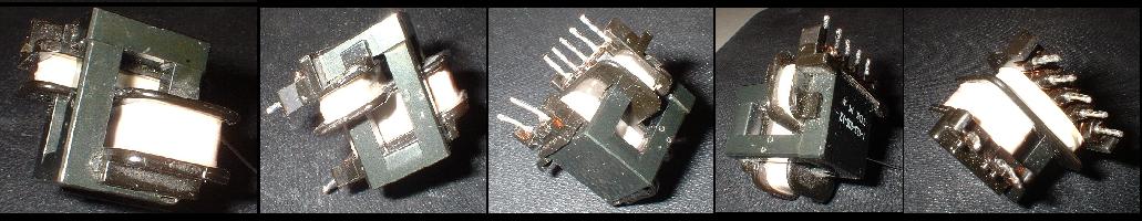
Such a device is shown, in several different views, to show that this is not any kind of a normal transformer. For instance, the small coil is gapped to 2.5 thousandths of an inch with gapping tape, the large one is not gapped, suggesting the large coil is designed to saturate the portion of the core not shared by the small coil. Such an arrangement will still affect the small coil, by altering overall characteristics of the device as two of the four legs of the core go into saturation.
Forget the notion of primary and secondary, those things are just names in a simple two winding transformer, indeed; you can take two identical 110 volt step-down transformers, even ones marked as Primary and Secondary and wire them up so that the two secondaries are connected together. Plug one of the so-called primaries into the 110 volt wall socket, and measure the voltage of the other unused primary, and you'll get back your 110 volts AC. Now I submit to you which is the primary, and the secondary of the second transformer? Oh you say, they've swapped, the primary, is now the secondary, and the secondary, is now the primary. Sure I say and the second one is now a step-up transformer. So what have we learned, simply this, it's how they're used, that determines which they are. Where primary versus secondary do come into play is when one input winding has to power a myriad of output windings, there the meaning is clear, input is primary, and the outputs are secondary. The one possible exception might be multi-kilowatt transformers, where wire heating is enough of a factor to make a difference. The overriding factor is that fine wire is delicate. Transformer bobbins are wound with the most fragile tiny thin wire first, often hundreds of turns of wire, then a layer of tape, and the wire is at this time also stripped and soldered onto the bobbin terminal lugs, and then the heavier gauge windings are spooled onto the bobbin, soldered, taped, and finally the heaviest wire used goes on last. This last outer winding is often only a few turns, I have seen a single turn of 16AWG wire used in some cases. These may be deceptive, often half a dozen strands, each individually enameled, dried, and twisted together to form a single multi-strand type of wire, called Litz wire that also minimizes electrical skin effect, and mechanical abrasion as well.
I mention all of this because one of the richest, and varied sources of ferrite transformers is your old junk drawer. Winding a transformer from scratch is, considering windings that are thousands turns, a lot of work. However if you only had to unwind a few heavy windings, and rewind your own custom windings onto them, you could have a custom built transformer without ever messing with that first winding with hundreds, if not thousands of turns to deal with. You can get the turns ratio before you mess with it, by pumping an appropriate frequency from a signal generator, into the high turns winding, and then with a sensitive AC volt meter or an oscilloscope, measure an outer low turns count windings AC voltage. The ratio of the input versus output voltage will give you the turns ratio. By unwrapping a few turns of wire, from the outer windings, and keeping a count of the winding whose voltage you measured, you can cross-multiply to get the number of turns the innermost winding holds. Now you can calculate the number of turns to put back on. Adding and removing turns of a finished transformer, should be avoided, since most of the time they are glued together, then dunked in varnish, and baked. But a few turns, well that's doable. Most of the time just locating the right one, especially if your selection is large, gets you close enough to get the job done.
Another way to get the number of turns on that unknown bobbin, you wind some additional known number, like say 10 turns for instance, pump some signal from a generator, while monitoring the output, of the 10 turn reference winding with a scope, while turning the frequency dial on your signal generator looking for a maximum voltage rise. Next look at the ratio of input voltage, to output voltage, this is the same as the turns ratio, and since you know how many turns you wound for a reference winding, 10 in this case, you can cross-multiply to get the unknown number of turns. Now you may unwind your test reference winding, compute the number of turns needed to maintain the various turns ratios, and then by trying to stuff various wire gauges, through the available window area, that's the space between the ferrite wall, and the last winding you can get some idea how large a wire to use. There exist formulas to get the wire sizes mathematically, but such formulas have rather nebulous ideas about how wire, and tape tend to "bunch-up" on a bobbin. My advice use your gut instinct, and be willing to unwind a few windings. Also don't forget you can sometimes add a few turns to an already existing winding.
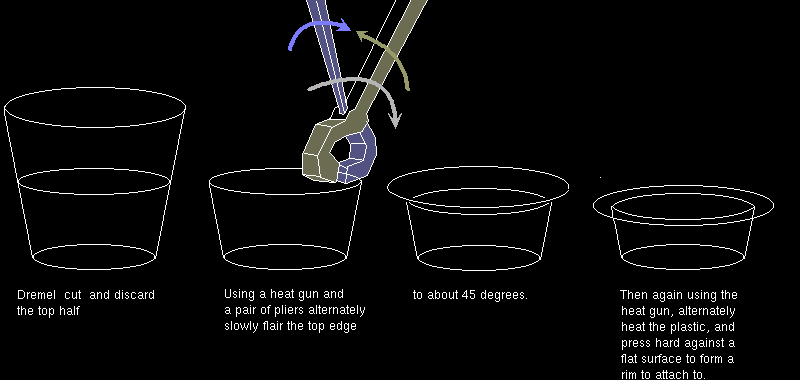
I needed something I could use as a protective cover for the LEDs, something that was strong, yet flexible enough to avoid being shattered on impact. I settled on an unusually thick walled mouth wash measuring cup. It had to be cut off, and the bottom edge flared out a bit to facilitate mounting.
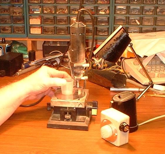
I once said of Dremel tools in the Tool Abuse section of this webpage, that it's one of those tools you'll wonder how you ever got along without.
Using a Dremel drill press with an abrasive fiber cutoff wheel and the vertical axis locked at a carefully chosen height, and the Dremel motor set to a relatively low speed, gently twirl the work piece, in this case a clear plastic mouth wash measuring cup, such that a very small amount of cutting is done in quarter-turn increments. For each full rotation of the work piece the fiber-stone cutting wheel cuts ever so slightly deeper, and after a time the two halves of the plastic cup remain fastened only by the thinnest possible strand of plastic. It is at this point that the greatest risk of injury exists from the work piece getting away from you. What I'm about to say probably goes against common sense, but if you think about it for a little bit, actually makes more sense. Fight the natural redundancy to grab more tightly to keep it from getting away. Seriously, what's it going to do, shoot you full of holes? No. Touch it to the stone with only the lightest possible touch, work slowly, and don't hang on, let it go if it wants to break free. It probably won't even fall off the Dermal drill press, let alone the work bench and even if it does fall to the floor, just grab it and continue, but don't take your eyes off the drill press until you turn it off first.
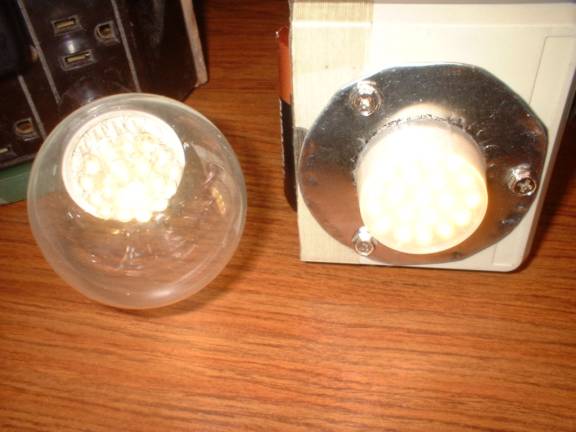
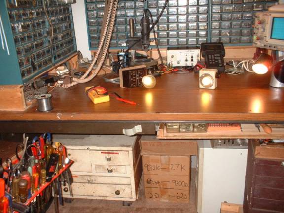
Here I try to compare the now finished LED flashlight to other light sources. The above photo is a closeup; the photo below is shot at a good distance to include other background, my workbench where this hobby project came together.
Click on above photo to zoom in.
In this photo light is reflected off the workbench, comparing the LED flashlight's brightness to the other light sources. The reflections are not as bright as the direct light sources, and as a result they don't overdrive the camera's imager, giving you one more chance to see the relative light intensities.