Alert!
This lesson's lab experiment uses dangerous voltages, and currents.
If performed incorrectly your likely hood of survival is rather low.
Performed correctly, using the precautions I describe here in, raises your
likelihood of survival to a level comparable with walking across the street,
on a green walk light, or driving down the freeway at a safe and prudent speed.
People still get squashed by a bus walking across the street, while doing
everything in their power to observe well known safety rules, and while
employing common sense. Safety rules do not guarantee survival, but they help
tremendously. Furthermore upon hearing of news that someone was squashed by
a bus while walking across the street, seldom deters onlookers from walking
across the street an hour later, they simply look death straight in the eye,
and stare him down, resolving to do everything in their power to avoid getting
squashed, but not to the exclusion of walking across the street, they merely
do so carefully. The danger this experiment exposes people who carry it
out to, will probably kill one person in 10 billion, even though they
meticulously follow my instructions. If these odds are too great for you, my
advice is to become a shutin, never venturing out into the dangerous world
around you, and stop taking this course. Life is a "Calculated Risk" there are
no guarantees, not even that you will survive. I offer no guarantees that my
experiments are safe, indeed, I am telling you that they are not safe.
That said I do my best to outline reasonable precautions that will greatly
increase safety, but the risk is yours, I cannot be responsible for the myriad
of mistakes people will make. If I tried to plan for every conceivable
eventuality, one, this web site would never be completed, and two, every
contingency planned for, potentially introduces
even more risk so such
planning is doomed to failure anyway. This experiment, as do all of my
experiments, teaches something important, this one demonstrates in a very
enlightening, and hands on way, the difference between reactance, and
resistance. It leaves a lasting impression of just how different they really
are, but to do this requires several watts of electrical power, at voltages,
that are high enough to be dangerous. Using lower voltages would make the
experiment unreliable as obtaining the specialized components could not be
relied upon in the kind of setting this Web based course is designed to be
used in, where you the student are required to locate all of your own
components. And let's not forget, someday sooner or later, you will have to
work with dangerous voltages, better you become familiar with techniques
that can offer a reasonable margin of safety now, in a somewhat controlled
setting, than later in a setting where a snap decision proves fatal.
If you feel uncertain about any of the safety information I provide, talk to
someone who is experienced in working with electricity to get clarification
on the points you are fuzzy on. Make sure you understand the "whys" of the
dos, and don'ts before you attempt the experiment.
Under no circumstances perform this experiment without listening to all the
audio, critical safety information is contained in the MP3 audio that is
part of this page, among other things I discuss the three levels of
separation, some people call "Fail Safe" that must be observed at all times
when working with dangerous voltages. To be electrocuted all three have to
breakdown, this is what gives you relative safety. I go way overboard on this
but I assume you are a novice, and as such, since I cannot be there to watch
you, the best I can offer are a set of rules, silly as they may seem, they
are not silly if they save your life. Sooner or later you will have an
incident when one of them break down, the other two, because they were in
place, are what is saving your life, later when you have time to reflect
you will understand why they are not so silly after all.
In the audio I discuss having a onlooker in the room to break the circuit,
and render assistance should the need arise. Make sure that this person knows
that they are to pull the plug of the extension cord from the wall socket,
not the table leg end, in the event of a mishap, and that they are not to
touch you, until the flow of current has in this prescribed way been stopped!
If they were to touch you... and this is what an untrained person is likely
to do, because they instinctively will attempt to pull the victim away from
the live wire. Doing this will likely get them electrocuted as well! Make
sure they know how to contact emergency medical assistance by phone, and if
they are trained in CPR, Cardio Pulmonary Recessitation, so much the better,
but call before attempting recessitation, and when they place you on hold,
turn on the speaker phone, and attend to the job of recessitation.
Click the "Audio discussion" link now, then
read on while it's downloading. When it
arrives, come back here, to start, and as I
progress through the audio discussion, I'll
instruct you to proceed from one pictorial
to the next, like a slide presentation
014_Setting_up.mp3 Audio lecture
on setting up a high voltage work area 8.79 meg
Experiments using real electricity
Your Notes:
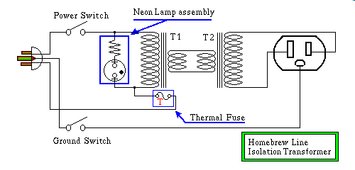
This lesson segment is nearly all lab, and when you complete this lab you
will have some additional useful test equipment. The first item, the
Home Brew Isolation Transformer, is to be built only if you
have on hand, two large, eg. in the range of 300 VA, eg. 300 watt, or above
nearly identical 120 volt primary to some other voltage secondary
transformers. If you don't already have a couple of these sitting around
unless you happen onto a couple of them, real real cheap, you are probably
better off buying an isolation transformer. Mouser has one for $62.16 that
delivers 2.1 amperes, and considering the effort you'll put into building
one, you better not have paid very much for the two transformers that makeup
this project. What is meant here by nearly identical, is one, the VA ratings
are within a two to one ratio, one to one is ofcourse best; and two the
secondary voltages of these transformers is within a ratio of 1.0:1.1 that
means as an example, that if one of the transformers secondaries was 24 volts
at 15 amps, and the other transformer was 28 volts at 25 amps the pair would
not be suitable for this use, because 28 divided by 24 is 1.1667 and that is
just too high, even though the power levels are fine. 24 times 15 is 360 watts
which is plenty of power to build a 200 watt Isolation Transformer.
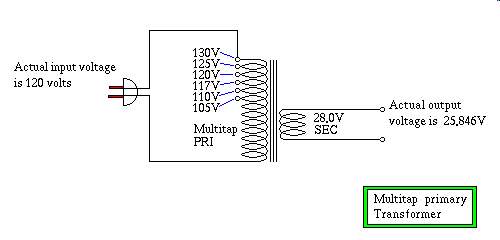
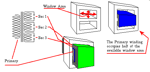
However upon looking at the primaries of the larger one, you happen to notice
that it's primary has an extra set of terminals for a tapped primary input
voltage that will allow an input of 130 volts. See the second picture in this
page, titled "Multi-tap Primary Transformer" Upon running the ratio numbers
you would discover that deliberately setting the wrong tap, making the
transformer a 130 volt primary, and then running it on 120 volts, a lower
voltage than it was designed for won't hurt anything, and it changes it's
output voltage from 28 volts to 25.846 volts. Now the voltage ratio of the
two transformers is 25.846 divided by the other transformer's secondary of
24 volts gives a ratio of 1.077 to 1 which makes it a perfect choice. It will
run the small transformer a little bit hard, but losses in the total system
will be somewhat canceled, by the fact that you are driving it a little harder
than the absolutely correct voltage.
A safety issue here to consider is that if the secondaries are a high voltage,
like say 700 volts, you probably shouldn't use these transformers as a
Home Brew Isolation Transformer because if the insulation
should break down, or moisture were to condense in just the right places
the isolated secondary could be giving off a very high voltage with respect
to earth ground. I mention this here, primarily because one might be tempted
to use a pair of transformers culled from two old worn out Microwave Ovens.
This is tempting because they handle about a thousand watts, and you could
easily build a five hundred watt isolation transformer from two such
transformers. My feeling is that it isn't worth the risk, I wouldn't use
a transformer for the purpose of building a
Home Brew Isolation Transformer
that stepped up more than double the line voltage as a rule of thumb.
Using step down transformers for this purpose is always safer.
I have found sources some of the parts for this and other experiments. I am
not necessarily recommending them, just mentioning them as a possibility, you
should scout out your own home stomping ground for sources of these materials
and don't overlook Flea Markets, Ham Fests, and Army Surplus stores.
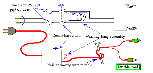
Switches suitable for the Dead Man switch
-------------------------------------------
Vendor      stock nbr   rating        price
Radio Shack 900-8572   6 amp/250 volt  3.69
Mouser      103-4025   6 amp/125 volt  3.18

Thermal fuse suitable for Isolation Xfmr
-------------------------------------------
Vendor      stock nbr   rating        price
Radio Shack RSU 11308467   189 deg F   1.29
MPJA        5357-TF        91 deg C    1.00

Neon indictor lamp assy
-------------------------------------------
Vendor      stock nbr   rating        price
Mouser      36HN010   110 volt         1.82
About the Mouser 103-4025 switch, neither the Mouser, nor the Radio Shack
version, is a true push button, rather both of these are
"Momentary Toggle" switches, that is they have a spring action that
upon release return them to the previous position, the Mouser version offers
a small safety feature in that it's lever is made of insulated plastic.
As an alternative you could mount two SPST Pushbutton switches, one on each
side of the box, arranged so that your thumb and forefinger can press both
buttons simultaneously, in a squeezing motion.
Oops I just threw in a another term you might not be familiar with, what is
SPST, it stands for Single Pole Single Throw. Ya' fine you say now that does
that mean, Ok Ok I'll get there. You will see switches designated by
acronyms like SPST, where sometimes the "S" is replaced with "D" meaning
Double. Think back to the days of early electrical experimenters, most famous
among them being Doctor Frankenstein, or maybe Dr. Tesla comes to mind, not
that he was ever on a par with the other :-) In their labs when Hollywood
needed to Juice things up there was the closure of this really nasty,
menacing looking Knife Switch, that always went sparky sparky when it was
operated. It is that Knife Switch that will serve as a good memory gimmick
to help you keep straight what things like SPST means. The Poles, are the
Knife blades, that swing from one throw to the other, in a real Knife
Switch, the kind Hollywood uses for effect they look like Poles pivoting
on the center contact. The action of Throwing the Switch, is that of moving
the Pole to a different Throw. Therefore a Double Pole switch is one that
has an insulator bar with handle, that links both poles together so that
the hand that throws the switch causes two circuits to change simultaneously.
A Double Throw switch is one which has contacts on both of the positions
that the switch can be toggled to. As an example the four wire pushbutton
switch I show as the Deadman Switch is a DPST switch, as an exercise to
insure you really grok this stuff, a DPDT has six wires, a SPST is a two
wire device, a the SPDT is a three wire switch, a SP6T is probably a rotary
switch, the kind with a knob, and six positions, and it has seven wires.
Similarly a 4P12T switch has 12 positions and 52 terminals for wires, think
old fashioned mechanical TV Tuner, my were those things complicated!
The MPJA (Marlin P Jones and Associates) 5357-TF thermal fuse has a screw
mounting ear to fasten it down the thing, in this case the transformer,
that is to be protected from overheating. The radio shack thermal fuse
poses an interesting problem, to pick up temperature it must be provided with
a thermal connection to the thing that is to be protected, on the other hand
it's body is electrically connected to the AC power line! So you need a very
special electrical insulator. While it must be conductive of heat, it must
not ever become conductive of electricity, this is especially vexing because
many such thermally conductive, electrically insulative materials, melt at
high temperatures. Melting would allow the body of the thermal fuse to make
contact with the body of the transformer, causing it to carry the dangerous
AC line voltage. There are special heat conductive Epoxy compounds designed
to address this need, and there is a product called Silpad which is an
adhesive backed sheet material, looks rather like adhesive tape, that is
impregnated with thermal conductive Silicon. The Silpad samples I have seen
are about as thick as Duct Tape, and are pre cut into various shapes, placed
onto Release Paper, like Postal Stamps. If you were to cut a strip out of
a coffee can a half inch wide, and 1.5 inches long, you could drill 3/16"
holes in the ends, and bend it into a "P" shape clamp around the electrically
hot thermal fuse, that has been prewrapped with Silpad, and the wire ends
should be covered with shrink tubing after soldering insulated wires to the
ends of the thermal fuse.
Assembly of Isolation transformer
The material you would choose for an enclosure for your homebrew isolation
transformer should be plywood, Masonite, or plastic. Do not use metal, the
whole reason for building an isolation transformer is to block a direct
path of current from the powerline to you. Each of the two transformers
are capable of providing a level of isolation, unless... If you mount them in
a metal enclosure, the enclosure itself can provide an unfortuitous path
bypassing part, or all of the isolation. On the other hand, wood is a fire
hazard, it's a little like having to choose between the lesser of two evils.
That's why I spend so much time on thermal fusing the power input transformer.
Transformers are particularly problematic from the standpoint of fire safety.
If a short circuit between any two adjacent windings inside the transformer's
coil occurs, what you have is the mighty output of the entire transformer,
its combined turns ratio, of its primary winding stacked against that single
shorted turn. The shorted turn can be anywhere in the transformer, primary
or secondary, the end result is the same. The entire output is diverted into
this lone shorted turn. Such a single turn produces a very low voltage,
usually a small fraction of a volt, at hundreds of amperes. The result is
that it gets incredibly hot, and melts away all its insulation, and
the insulation of nearby as yet undamaged windings. They too ultimately
short, and now contribute to further destruction of even more nearby windings.
This shorting of adjacent windings is not unlike a cancer of the
transformer, and it spreads until the primary draws so much current that
a wire burns open, or a fuse, or, circuit breaker blows. What you may not
understand is that a transformer fused with a current limiting fuse, can
because of this process, long before the current limit of the fuse is reached,
create so much heat that the transformer will glow yellow hot! Such
a transformer mounted to wood, can start a fire. That is why I spend so much
time giving information of proper thermal fusing, a thermal fuse doesn't blow
because the current has been exceeded, it blows, or opens because its
rated temperature has been exceeded, which is precisely the proper way to fuse
a transformer, then if you want to put in additional fusing, in series with
the thermal fuse that is up to you, but the thermal fuse is critical.
The base of the Isolation transformer wooden enclosure should be made of a
thick plywood baseplate, say one inch thick. The sides, front, and rear, can
be thin quarter inch plywood, or eighth inch Tempered Masonite, and Masonite
is easy to work with, and looks good unpainted, however the top should be
made of five eighth's inch plywood because this allows you a solid cross
sectional area to sink your wood screws into for fastening the sides, front,
and rear, panels. Finally place corner molding pieces in all four corners to
provide solid pine to allow something for wood screws to sink their teeth
into for fastening of the sides to each other. The base of the enclosure
is ofcourse the surface that you mount down all of the heavy components to,
such as, and especially the transformers. None of the screws should be long
enough to protrude through the bottom of the cabinet, not only is this a
potential electrical safety issue, but wood screws have sharp points, and
sliding a heavy wooden cabinet with a sharp screw point sticking out of the
bottom, will marr the surface of your nice Formica top, in a way that
finished plywood by itself will not. The outlet receptacle should be
mounted to one of the sides, being they are smallest Masonite plates, and the
plate that holds the electrical outlet should have enough screws to hold it
securely while things are plugged into, and unplugged from the electrical
outlet that it is supporting. For screws consider using hardened steel drywall
screws, these have a very aggressive thread pitch, and are kind to wood, in
that they seldom cause it to split. If you are of a mind to use glue, I
recommend building this cabinet in two pieces that fit together, one piece
has the bottom, and the end with the outlet mounted to it, and the other is
the the top, and the other walls, should repair ever be necessary, you'll be
glad you made it that way. As for the wire that connects the two low voltage
windings to each other, this needs to be very heavy wire, the lower the
voltage they are, generally speaking the heavier the wire, a good rule of
thumb is use wire that is atleast three gauge sizes lower, than the wire
exiting the transformer. Note the lower the gauge size the larger the wire.
By using wire three gauge sizes lower, you nearly double the cross sectional
area of the current carrying copper wire.
Construction Notes:
Many of the construction techniques I show here are useful everywhere
electronics projects are built by hand, therefore you should create a separate
file in your "Electronic Notes" directory specifically for construction
techniques, keep in mind my warning about
avoiding Proprietary Formats
from the end of lesson 010. It may sound a bit preachy, but the advice is
essential to any creative endeavor, and this course teaches creativity,
disguised as electronics. Maybe that is too strongly worded, you may have
heard that creativity cannot be taught. I for one believe this to be true,
but I also believe that genuinely creative people are easily duped into
pursuing a life in which, their creative potential is never realized.
Oh and by the way if you haven't already done so take a gander at
my tool abuse page
it shows how to think like a tool maker, as opposed to a tool user.
For those of you running some variant of Unix, in the "X" window system,
it can be handy to open multiple "Desktops" simultaneously, one catering to
applications and files dealing with hardware notes, purchasing of, or
acquiring free samples of parts, a drawing package for maps, and other
doodles, and so forth, and another desktop for the study of electronics
itself, and yet another for the browser, and its ancillary windows, this
gives a nice uncluttered appearance, and beneath all of this are a dozen
or so virtual terminals for those nice crisp Emacs screens that GUIs will
never touch, oops way off the track, back to the project
Assembly of Suicide Cord
After building the Suicide Cord, you need to test it to be sure it is reliably
safe to use. First a visual inspection before the box is closed up. You are
looking for anything that could create an unplanned path of current.
Multistrand wire poses a danger if a stray thin strand of wire accidentally
makes contact with something that could carry current to you. Even if not
actually touching something now, after the box is closed the wires may move,
and if it were to make contact with something made of metal, such as the body
of the switch you could get a shock from the push button itself. Use wire
cutters to snip off any such stragglers, and use
this technique to
make a good solder connection in tight places.
Make sure that all cords entering
the box have some kind of strain relief. I will explain... The term Strain
Relief is, in this sense taken to mean, the point where the wire makes entry
to the box, the wire is securely fastened to the box such that a good hard
yank on the cord cannot disturb the wiring inside. One way to accomplish this
is to, prior to wiring the box up, drill a hole through the box, where you
want the cable to enter the box, the hole should be no bigger than necessary
to accommodate the wire with heated shrink tubing covering it. Next slide the
wire into the hole, and from the inside of the box grab hold of the wire, and
pull several feet of it through the hole. Now select a piece of shrink tubing
that is about 4 inches long, and no larger than needed to fit around the cord.
Slide it back about nine inches from the bare end of the cord. Now tie a knot
in the cord, shrink tubing, combination such that the knot is centered so
that there is a half inch of tubing extending from the knot toward the bare
end of the cord, and the remainder of the tubing, probably two inches or so
is extending toward the box, and plug end. Tighten the knot. Now heat the
tubing with a butane lighter, with a smooth waving motion as you rotate the
cord back and forth to distribute the heat of the flame evenly, so as not
to scorch the shrink tubing, or the electrical cord. This will shrink the
tubing down around the knot, and the cable, and when it cools it will be
somewhat stiffer. Next pull the cable back into the box so that the knot
rests against the inside wall of the plastic project box. Now use a Hot Glue
Gun to anchor the knot securely to the plastic project box inside wall.
Note: Rubber cement will work also but I caution you not to use Silicon
Rubber glue, because it gives off Ascetic Acid vapors, long after the project
is completed. These vapors over time will penetrate the enclosure of the
switch and corrode the electrical contacts inside, rendering the switch
useless, and perhaps dangerous.
After the glue sets up, on the knots of both cables, and the box is wired and
inspected, place the lid on the box, and screw in the corner screws. Now you
are ready to perform a continuity test. Connect both clipleads together, and
and clip them to one of the prongs of the plug, and use a separate clip lead
to clip both ends of the plug prongs together, and clip the common wire of
your Multimeter to the same mass of interconnected plug prongs, and clip
leads. Set the meter to the highest Ohm scale possible, probably Rx10000, and
momentarily test the meter by touching the other meter probe to a different
point on mass of interconnected plug prongs, and clip leads, just to see that
the setup is working. Now touch that meter probe to every metal object on the
box, one object at a time, watching the meter, for any sign of conductivity.
Do this once with the button released, and once with it held down. You are
testing for any unforeseen electrical path to the surface of the box.
Next unhook every thing, now connect one clip lead across the two prongs of
the plug, and both clips exiting the Suicide Cord to each other, place one
meter lead on the Suicide Cord's plug end, and one on the joined clips.
This should show an open circuit while the pushbutton is released, and
a closed circuit when it is pressed.
Next disconnect the meter leads from the Suicide Cord, now separate the clip
leads exiting the Suicide Cord from each other, and connect one each to the
two meter leads, leaving the lone clip lead that is joining the prongs of the
plug together, connected. Once again the meter should see an open circuit
when the button is released, and closure when it is pressed. If these checks
are good, as a last test set the Multimeter to the lowest resistance range
probably Rx1, touch the probes together, to allow you to zero the meter, and
then open them. Now pressing the button should read no more than a tiny
fraction of an Ohm. If all these tests pass your box is ready for the final
live test.
Live Test:
Get a working table lamp, plug it in, switch it on to insure it lights.
Unplug it while it is working, and clip the two clip leads of the Suicide
Cord to the prongs of the lamp's plug. Now observing all of the safety
rules, and with an informed onlooker present, plug the Suicide Cord into
the extension cord hanging from the table leg, nothing should happen, if
anything happens pull the Suicide Cord's plug out immediately.
Let me elaborate:
As you plug it in be anticipating nothing, psych yourself to reflexively
pull the plug out, as an automatic response to any kind of reaction, if
the toilet flushes in the next room, just as you plug it in, and you
reflexively yanked the plug out, because you heard something, after you
calm down, you can always do the experiment again, once you've determined
that the toilet had nothing to do with your experiment.
If this phase of the test went Ok, press the push button, both the lamp,
and the Neon warning lamp in the Suicide Cord's control box should light
when you do this. Release the push button, and reach up and turn off the
switch on the lamp, the Neon warning lamp should remain out, and it, and only
it, should light when you press the button this time. Now for the final test
press the button to insure that only the Neon warning lamp, lights as you push
the button, and extinguishes when you release it, the table lamp should
ofcourse remain out during this phase of the test. Now pull the plug of
the Suicide Cord out of the extension cord's receptacle. If this phase of
the test went Ok you now have a tested Suicide Cord, use it with care.
What the final phase of the test is doing, deserves some explanation. Earlier
tests determined that the push button switch when closed, could indeed deliver
enough current to the clip leads to operate a substantial load, in this case
the table lamp. The final phase of the test insures that with no load applied
the Neon stays out, the reason for pressing the button, is to insure that
the table lamp is indeed switched off, some table lamp switches, are designed
for three way bulbs, and if you had one of these, and someone unbeknown to
you, had inserted a regular light bulb, you may think you turned it off,
without actually doing so. Pressing the button, the last time, expecting only
the Neon to light, will alert you to this, allowing you to get this final
phase of the test right. The purpose of this final phase, is to test your
control box, especially the switch, for leakage current. If leakage current
is low enough to prevent a Neon Glow Tube from lighting, it is below the
level that is dangerous to people.
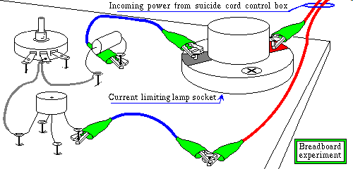
Now you are ready to setup your breadboard. I will assume you have read
through this entire page, and acquired the necessary components to build it.
I show below a breadboard partially wired up for the first phase of the
experiment. This is not intended to show you how to wire it up, that's
what the diagram is for, rather this is to show in a general way how to
make connections to nail heads, and device terminals, and the like.
Start the download of the audio discussion, now while looking this
experiment over, and when it starts playing place the drawing for the
"Breadboard experiment" in the center of your browser's screen.
014_HV_bred_bord.mp3 Audio discussion
of high voltage breadboarding 8.41 meg
http://www.leviton.com/sections/prodinfo/lamphold/laframe2.htm#cats
Porcelain and Phenolic Lampholders
Pony Cleat Type                           Dimensions in inches
DESCRIPTION             CAT #    RATING      OD     OH       C
Candelabra Base Plastic 10028  75W 125V  1 7/16    7/8    11/8
Miniature Base, Plastic 10020  75W 125V  1 5/16    7/8   31/32
Medium Base, Phenolic    9063 660W 250V  1  7/8  1 1/2  1 5/16
Medium Base, Porcelain  19062 660W 250V  1  7/8  1 1/2  1 5/16
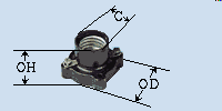
Leviton 9063
A word about using a light bulb as a current limiter. If you measure a 100
watt light bulb with an ohm meter, you read about ten ohms, and if the bulb
were to stay at ten ohms, when plugged in, it would draw 1440 watts! Cold
filament resistance is much less than when it is hot, which makes it much
more like a wire when it is cold, but still is useful as a current limiting
device. I re-iterate this here, because I have some very
interesting formulas that
allow you to calculate things like the actual bulb life you will get
if you operate the bulb on less than it's design voltage, or what
resistance its filament will provide at differing voltages, and so forth.
-------------------------------------------
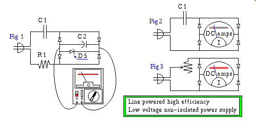
Components needed for this experiment:
An inclosed internal cabinet wiring type
120V light socket, eg. it should look
like the one in the illustration above
Leviton Corp. Catalog number 9063
100 watt 120 volt light bulb
A 2 or 3 amp fuse that fits in light socket
C1 - 1.0 microfarad 250 volt capacitor
1.5 microfarad 600 v will also work
R1 - 3000 ohm 3 watt potentiometer
3500 ohm 5 w will also work
1.0 amp 200 volt Diode bridge
4.0 amp at 600 v will also work
Ancillary materials:
Wood screws for fastening the light socket
20, approx 1 inch long, flat head nails
10" by 15" by 1" thick piece of plywood
Some hookup wire
Some Alligator Clip Leads
One assembled and tested Suicide Cord
A good reliable VOM (multimeter)
A sturdy worktable with an insulated top
A heavy duty extension cord
-------------------------------------------
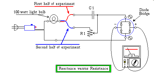
Ok so wire it up, and use the red link wire, shown in the Resistance versus
Reactance diagram connecting the light bulb to the capacitor, omitting the link
wire shown in blue, that one is for the second half of the experiment. The
red, and blue links are, in reality, most likely, going to use the same
alligator clip lead, in both halves of the experiment, the only difference
being that in one, the clip is connected to the capacitor, and in the second
half it is connected to the potentiometer.
It is standard industry jargon to refer to capacitors as caps, and
potentiometers as pots. I will at some point dispense with the long form, and
so I air this now to avoid confusion later.
Now look at your breadboard, and imagine what you would do when you unclip
the alligator clip from the capacitor, and connect it to the potentiometer.
There are three terminals on the potentiometer, this experiment uses only two
of them, the choice you make of which of the two remaining terminals to use
determines whither clockwise, or counterclockwise rotation of the pots control
shaft causes the resistance of the pot to increase or decrease. Put in other
words, if you connect say the middle terminal, and the left terminal to the
ohm meter and start turning the knob for maximum resistance, if you then were
to connect the meter to the middle and right terminal you would see nearly
zero ohms. As a critical step in the preparation of this experiment you
need to mark, read this get out your sharpie, or magic marker, and some how
draw arrows near the pot, pointing to the terminal you intend to connect the
clip lead to, when the second half of the experiment is performed, and draw
an arrow that indicates which direction the knob needs to be rotated to
achieve maximum resistance for your chosen clip lead connection. As the final
step dial it to maximum resistance, and be sure you know that you are reading
the resistance scale, they are usually ordered in the reverse of all the
other scales. If you get this wrong, you will likely burn out your meter,
later when you go to do the second phase of this experiment.
A word of caution:
If you have selected the Range Doubled 43 Range Multitester that Radio Shack
puts on sale from time to time, I mention this one because I have information
on it, the zero ohm current at the probes of the meter, when set to Rx1000
is 0.125 ma, and at
Rx100 = 1.25 ma and at
Rx10 = 12.5 ma and at
Rx1 = it's a whopping one eighth of an amp!
I'm about to show you an extreme however very common example, of how
destructive a simple ohm meter can be to components you might want to measure.
Let's say you have a one megohm, half watt pot, and you dial it all they way
down to as low a resistance as you can get, you'd be lucky to get it down to
50 ohms, ok so 50 it is. The formula for power is P=(I^2)*R if you know the
full scale zero ohm current, you can read the current directly off the dial
of the multimeter, by reading a scale of that range. In this instance 50 ohms,
at a scale setting of Rx1 draws 20 ma, and 0.020 squared is 0.0004 times 50
ohm is 0.02 or 20 milliwatt. That doesn't sound like much, but just wait till
you see what it's going into. The one megohm half watt pot, is dialed down to
50 ohm, thus only fifty millionths of the carbon resistance element is
available for dissipation of power. Since the whole pot is a half watt pot,
the active area of the resistance element is only capable of 25 microwatt,
and the power the ohm meter is applying to the poor defenseless little pot,
is nearly a thousand times greater! Can you say poof. In truth it would take
Hollywood Pyrotechnics to produce anything visible, however this does indeed
damage the pot. The damage manifests itself as erratic operation near the
damaged end, as the wiper arm makes intermittent contact with that area of
the resistance material that has been scorched.
A little common sense here is required, measure the far two terminals of the
pot if you don't already know how many ohms it is Stop to Stop.
Then if you want to measure the wiper arm through the resistance element to
the end terminal, with your handy VOM, if while measuring the resistance
of a pot, as high as 2.5 megohms, should you have this uncontrollable urge to
dial it down to zero, use the Rx100 scale. I give you a table of ohmmeter
range settings that should not be too destructive for the short duration of
time it takes to make a reading. These guide lines at their extremes, stress
the pot at a rate four times the pot's wattage rating, but all the heat is
concentrated in such a small area, that it will most likely dissipate
without doing any noticeable permanent damage. Remember the Range Setting
shown is the lowest range setting that you should be using for a pot
with less than or equal to a full Stop to Stop resistance, shown
in the chart, and of a given wattage greater than or equal that shown in the
chart.
-------------------------------------------
1 Watt Pots   1/4 Watt Pots   Range setting

ridiculous    250 meg         Rx1000
10 meg        2.5 meg         Rx100
100 k          25 k           Rx10
1 k           250 ohm         Rx1
-------------------------------------------
These guide lines are loosely based on the aforementioned meter, loosely in
that, I try to take into account that the small size of the energy dissipating
region of the resistance element, will more readily carry heat off from the
affected area. Additionally the fact that maximum power transfer occurs at
fifty percent of the Thevinized voltage, or if you prefer Nortonized current
of the ohm meter's output. Thus the meter is at half scale when maximum power
transfer occurs, and on these meters, this point on the dial is ten on the
ohms scale, thus 10 ohms draws 62.5 ma on Rx1 dissipating 39 mw, 100 ohms
draws 6.25 ma on Rx10 dissipating 3.9 mw, and soforth, here's a table.
-------------------------------------------
Range         Resistance      Power
Rx1               10 ohm       39 milliwatt
Rx10             100 ohm      3.9 milliwatt
Rx100           1000 ohm      390 microwatt
Rx1000         10000 ohm       39 microwatt
-------------------------------------------
Electrical Safety note:
Use the same kind of procedure you used for checking metal surfaces of the
of the Suicide Cord's Control box, to check to make sure that any metal
surfaces you need to touch are not electrically connected to any of the
wiring. Especially the control shaft of the pot, because you need to turn
this while power is applied, in the second half of the experiment. Also
test the metal body parts, and if they show conductivity, make a mental
not to touch them while the circuit is powered up. Just as important is to
know what portions are insulated, because part of what you will be doing
is feeling it for signs of heat, eg. increase in temperature of about 20
Fahrenheit degrees, and you should know what is safe to touch, before you
get to that stage.
Contemplating the cosmic one-ness of the above experiment.
Ramifications:
As the experiment clearly demonstrates, a pure reactance does not dissipate,
or use energy, so you might wonder since it is drawing current, but not
power, can I draw current without spinning my electric meter. The surprising
answer to this question is yes! Electric meters are designed to measure true
power, and since a reactive load does not dissipate, or use power, they don't
register on an electric meter. That said, nothing is free, there is a price
for all of this, current is being drawn after all. So who pays? The electric
power utility, that's who. The additional current that your little reactive
load presented to the AC powerline, resulted in additional current flowing
through the transmission lines that ferry the power to your house. That
additional current passing through copper wires, that have resistance,
is converted to heat, and does require power.
The irony is not lost on Electric Utilities, they offer discount incentive
programs to major industrial users of electricity, in exchange for their
cooperation in maintaining balanced power factor loading on the powerlines.
It doesn't stop there, in Europe, and some other parts of the world, and
someday soon even in the US, laws are being passed that require balanced
power factor loading on any household appliance sold, above a certain wattage
rating. The wattage rating varies, from country to country, and is reduced
over time as technology improves the cost/benefit ratio, currently my
understanding is that some European markets require this on 50 watts or more,
but don't quote me on this, if you intend to design an apparatus for such a
market, check their laws, and get information on regulations still in
committee before finalizing your design, because by the time you gear up for
production you will probably be required to comply with laws, that at the
time you asked, were only a gleam in a law makers eye.
None of these laws apply to a one of a kind prototype apparatus, such a law
would stifle innovation, and be utterly unenforceable, many governing bodies
have tried to pass such laws in the past, and most have learned by experience
that unless a law has the backing of the large majority of the people, and is
technically capable of producing the desired result, it is ultimately
repealed, and all the expense trying to force the impossible to work, is
thrown away, a total loss. Law makers are believe it or not, even in
dictatorships, sensitive to these realities, they in some cases in a face
saving move, such as the failed " ", turn
a blind eye to these realities until such time that there is a consensus for
change. I am a guarded optimist, in the future we can hope these governing
bodies will take seriously the information that science provides, without
paying science to cook the results. Even middle managers can screw things up
though, Space Shuttle Challenger, and the Hubble Telescope were avoidable,
if only the middle managers would have listened. You have a duty to make
them understand, if you ever find yourself in such a position, exercise it,
because you can't undo tomorrow what you fail to correct today, and it will
haunt you for the rest of your life.
", turn
a blind eye to these realities until such time that there is a consensus for
change. I am a guarded optimist, in the future we can hope these governing
bodies will take seriously the information that science provides, without
paying science to cook the results. Even middle managers can screw things up
though, Space Shuttle Challenger, and the Hubble Telescope were avoidable,
if only the middle managers would have listened. You have a duty to make
them understand, if you ever find yourself in such a position, exercise it,
because you can't undo tomorrow what you fail to correct today, and it will
haunt you for the rest of your life.
I actually performed this experiment with two capacitors that I had on hand
with suitably high voltage, a 1.0 uf, and a 3.3 uf, both at 250 wvdc
(working volts direct current) and I used the measured current to calculate
the actual capacitance of them. Here is the results of that experiment.
Oh and one other little detail, a non-polarized cap that is rated xx volts
DC doesn't mean that you can't put AC across it, it just means that you
have to consider the "peak" voltage of the AC you are applying to the cap,
specifically if it is a sine wave, multiply the RMS AC voltage by 1.414 as
you learned in lesson 010, the lesson on Sine Waves.
-------------------------------------------
I measured 48 ma with the 1.0 uf
120 / .048 = 2500 ohm Xc
1 / 2 Pi 2500 60 = 1.06 uf

140 ma with 3.3 uf
120 / .140 = 857 ohm Xc
1 / 2 Pi 857 60 = 3.09 uf
-------------------------------------------
014_HV_bred_bord_4.mp3 Audio discussion
of high voltage breadboarding 4.07 meg
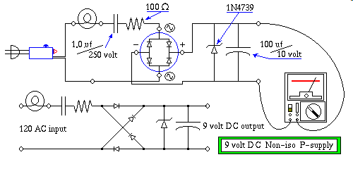
You may be wondering what the pot is doing in this circuit, the profound
answer to that question is nothing. But you say, it is shown soldered to
a wire and the 100 ohm resistor. Ok, not nothing, the pot's middle wire
is simply serving as a securely anchored terminal, but the pot itself is
not really part of the circuit, it's just a handy anchor point, oh and by
the way, don't forget to remove the grey wire that was there before the
resistor was installed in it's place, in other words, snip out the grey
wire that previously was connecting the 1.0 uf cap, and the wiper arm of
the pot.
Identifying windings of an unknown transformer
This subject is one of those things that when the pieces all fall into place
everything makes sense, and prior to doing that it appears to be a black art.
To really understand how to properly categorize an unknown transformer, you
need to think like the guy that designed it, and to do that requires a
rudimentary understanding of what tradeoffs are considered in such a design.
So bear with me, this will get a little strange. If you apply a small AC
voltage to one of the windings of a transformer, all of the other windings
will present at their various turns ratios, voltages that are ratiometric to
the input voltage you have applied to that one winding you are temporarily
using for a primary winding. Remember there really is no such thing as a
primary, and secondary winding, in a transformer in any absolute sense,
rather the geometry, or if you prefer the "bobbin window area" is divided up
to optimize for maximum power transfer, and using a secondary winding, as
a primary, has little effect on the transformers over all effectiveness,
unless it has a multiple secondary windings. Why? The designer of a multiple
winding transformer must set aside half of the available window area for
putting power into the transformer, the remainder if it is a simple two
winding transformer, will be a winding that is used to pull power out of
the transformer, a two winding transformer, read that, one primary, and one
secondary will operate equally effectively in either direction. However
if it is a transformer with two or more secondaries, say three by way of
example, what you have is three secondaries sharing the other half of the
available window area
In truth careful transformer design tries to take into consideration the
fact that layers of insulation use up window area, this is especially true
of multi winding transformers. So much so that a transformer with ten
windings has only about half the power output of a two winding transformer
of the same size and weight. Then there is the matter of wire resistance,
since there is more wire per turn the farther out you get from the center
of the transformer's core, the more electrical resistance you have in the
copper windings the farther out you get from the center. It would be a poor
design indeed if this were overlooked. A transformer not given attention to
this detail, is likely to be very lopsided, for instance, an isolation
transformer, if designed properly should have equal DC coil resistance
on both primary, and secondary. In fact if designed right, you should not be
able to distinguish between the primary, and secondary by any DC or low
frequency measurement you could make external to the transformer. So how
would a transformer designer go about getting the resistances to match in an
isolation transformer? The answer is, you would use smaller diameter wire
on the primary, because that winding is shorter. The smaller diameter wire
has more resistance than a larger diameter, but, being shorter compensates.
Then after it is wound, the secondary is wound on top of it. The secondary
is longer, even though it has exactly the same number of turns as the
primary. The added length means more copper wire, and more resistance, but
the fact that we are compensating by using larger diameter, eg. lower
resistance per linear unit wire, with any luck the two windings resistances
match perfectly. In practice luck has nothing to do with it, there are a
series mathematical formulas that determine what wire size to use to place
the transformer in proper balance. These formulas result in primaries that
occupy considerably less than half of the available window area as a
practical matter, but as a first approximation, the notion of the primary
occupying the first half of the window is more easily understood
Transformers in the wild vary widely, from one sub species to another. If you
ever see a transformer with a primary rated 120 volts, at 60 hertz only, this
is a transformer wound to run well into the saturation curve, and it will
idle hot, compared to it's international 50/60 hertz counterpart. By idle,
I mean power is applied to the primary, without any load connected to any of
the secondaries. A transformer rated at a given voltage, for 50/60 hertz,
means that it will run on either frequency, obviously if you run it at the
lower frequency it will run right at the onset of saturation, but if you live
in a 60 hertz country you will never see 50 hertz, and if the need arises you
can get an additional 15 to 20 percent more voltage out of such a transformer,
by running at a little higher input voltage, or setting the tap to a lower
value. If you do this it will idle about as hot as it would if it were
running on European, or Japanese 50 hertz current using its normal design
voltage.
Caution:
Idle any transformer you intend to do this to, for four hours, to allow it to
reach thermal equilibrium, before you wire it up permanently. And while
waiting for it to stabilize, touch the frame of the transformer under test,
every minute for the first five minutes, then once every five minutes for
the next half hour, then once every fifteen minutes for the next hour, and
then once every hour there after until you are sure it has gotten as hot
as it's going to get. It should get no hotter than a temperature that you can
comfortably hold your finger in contact with the frame for ten seconds.
If it gets hotter than that, you're pushing it too hard, back off on the
input voltage just a little, or set the input tap up one voltage above the
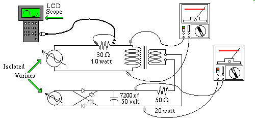
present setting. I show below a circuit to measure the current waveform of
a fairly large transformer running at the onset of saturation, followed
by the actual waveform itself.
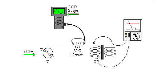
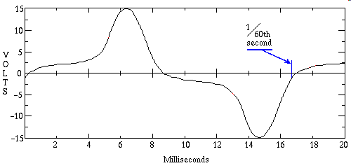
In the above waveform the variac is adjusted such that the meter reads
120 volts and the voltage plotted in the waveform is an indication
of the current flowing through the transformers primary, in that it is
a measurement of voltage drop across a series current sensing 30 ohm shunt
resistor. Thus from one millisecond to the next the current flowing through
the coil of the transformer's primary winding is charted on the Velleman
Hand held Liquid Crystal Display Oscilloscope. The Velleman has several
advantages over conventional oscilloscopes, plus a few draw backs. The main
advantage here is that I can plug the Velleman into the serial port, set
the port to 9600 baud, and the computer can read the waveform, as a list of
points, that various Math Visualizing programs can output as a dot png file
that your web browser can properly display. Another advantage is that it is
battery powered, while the actual measurement is taking place, thus there is
no possibility of a ground loop, that poses a danger to both men/women and
especially machine. I provide more on
the Velleman K7105 Scope
should you require such info.
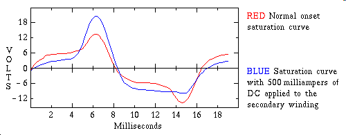
Notice that the waveform is anything but linear, a linear current waveform
would look sinusoidal, this one is anything but.
The next circuit is a variation on this one, I setup a DC power source that
can pump an average of 500 ma. into a 25 volt RMS secondary. The DC power
is composed of a smaller, I.E. lower voltage variac, that provides a
controllable AC voltage to a diode bridge, capacitor combination. The
capacitor is suitably large, such that it's impedance, or RC time constant
with respect to the resistor, is negligible. For our purposes it behaves like
a variable battery. The current from the variable battery is limited by
the series 50 ohm resistor, and I show the saturation waveforms for both,
where in case one, the variable battery is set to zero volts, but
still connected to the secondary through the 50 ohm resistor. And case
number two, where I actually pump the transformer's secondary with an average
of 500 ma. The result is a non-symmetrical saturation curve, shown in
blue superimposed over case one the reference wave shone in red. The
reason the DC powersupply and current limiting resistor remain connected
during the reference phase of the test, is to establish the primary current
waveform while the secondary winding is being loaded by the 50 ohm
resistor, failing to do this would introduce additional variables into the
experiment, when we went to the phase two, where we actually pump the
secondary winding with polarizing direct current.
Not to spend a lot of time on this, but earlier I mentioned the curiosity
of Polarized Inductors this experiment demonstrates the phenomenon,
by placing a direct current on one of the windings of a transformer, that
is otherwise being used as an inductor driven to the onset of saturation.
The direct current flowing in the secondary, replaces the permanent magnet
in the Polarized Inductor and illustrates the point that coils are
not so different from one another, in that they're behavior can be coaxed
into doing many specialized duties. A variation of this phenomenon is the
heart of a flux gate magnetometer. Oh there I've gone and done it, straying
way off the path, Ok back to identifying Wild transformers.
Ok now let's say you have a transformer of unknown origin, you can't even
be sure if it is intended to be powered off the line voltage. Well the first
thing you do is to ohm it out to see what paths of current flow between
the lead wires, or terminals of this undomesticated transformer. Draw a
diagram of the paths of electrical continuity, and write down their DC
resistances. As a final check test to make sure that there isn't a path of
conductivity you may have missed, remember often transformer windings have
many taps. If you encounter a single wire that appears not to be connected
to anything note this one with suspicion, it could be an interwinding shield
or maybe an open winding, most likely a burned out transformer. If you
encounter two such terminals, it is almost a certainty that it is a fried
transformer. If the transformer is fried, mark it as bad, and go on to the
next one.
Using an AC wall wart that produces six volts AC, power one of the medium
resistance windings of the undomesticated transformer. Measure the six volt
AC with and without the load of the undomesticated transformer's winding
loading the wall wart. If it droops below four volts AC, try another winding
of the undomesticated transformer. Now with the undomesticated transformer
winding connected to the six volt AC source carefully measure the other
windings of the undomesticated transformer, and write their respective
voltages down on your diagram. Do this carefully, an undomesticated
transformer can do anything turns ratio wise, it could boost that six volt
input up to hundreds of volts on one of the other windings, so treat them as
dangerous, until you have measured them, and know that they are not.
One way to gain experience with this phase of the procedure is to carry out
this procedure on a transformer that you really do in fact have data on, as
a dry run. Doing a dry run, is also useful at several other phases of this
procedure, that I have not discussed yet, so remember this if you have any
doubt about how to carry out one of the other phases of this procedure.
When you figure out the voltages of all of the other windings, with respect
to the one winding you are pumping with six volts AC, what you have is a
crude map of the turns ratios. If you have reason to believe this transformer
was a multi winding step down transformer, there will be one winding that
appears to have the highest AC voltage, when compared to all the others, and
it is likely that, that winding is the power input winding. If that windings
lead wires exit the transformer from the opposite side of the transformer,
from all the other wires, the likelihood is even higher. If the lead wires
are color coded, and the wires you suspect from your measurements are the
power mains, eg the primary winding of a line power transformer, and
those suspected wires are either black, or white, or some
striped combination of black, and white then it is a near certainty,
that you have located the power mains, of what is a line power transformer.
On the other hand, if this transformer is known to have been removed from
Vacuum Tube equipment, including Tube based Laser, high power Microwave,
such as Cavity Magnetron drivers, Neon Sign transformers, old Oscilloscopes,
that don't use a modern solid state flyback design, etc. the highest voltage
winding will likely NOT be the power input mains. For this reason it
is important if you are about to salvage a transformer from a piece of
equipment, to note which wires were connected to the powerline, before you go
cutting wires, and since the output voltages of the secondaries usually go
to diode bridge assemblies, whose DC output goes to a filter capacitor, it
will save you enormous effort if you note the voltages marked on those,
filter caps, and draw a little diagram of what winding they were connected
to, before you pull the transformer out. Cost containment prevents
manufacturers from placing radically higher voltage capacitors in a circuit
than are necessary, although they are often a third higher voltage, than is
actually applied, to allow for a safety margin in the event of overvoltage
operation, and voltage surges. Oh and a word of caution, especially on high
voltage equipment, if you suspect the unit has been powered up recently,
go in with an insulated handled screwdriver, and touch the blade across,
the terminals of all of the capacitors in the system, in other words short
them all out, before you get in there with your bare hands. Capacitors
can recharge on their own by a process known as Dielectric Charge Migration,
essentially a discharged cap can have regions within its dielectric that
each contain charges that neutralize each other, and if one leaks off, the
cap assumes the difference charge. While probably not terribly dangerous,
it might not be very pleasant. Also Tube based equipment is these days getting
to be rather scarce, so a transformer culled from such a piece of equipment
is a very valuable find. You won't often need high voltage, but when you do
there simply is no substitute for the good old transformer you culled from
that TV set you found in the attic last summer.
Ok we will assume you have figured out what you believe to be are the power
mains of this as yet undomesticated transformer. At this point you
can if you want play with the ratios arithmetically, to derive the actual
voltages that will be present on each of the secondaries, assuming you are
right about the selection for the power mains. In fact the ratiometric
derived secondary voltages, will not be right on the button, but they will
probably be fairly close. Ok now connect up your undomesticated
transformer, to the bread board, using the light socket as a current limiter.
You need at your ready disposal an assortment of different wattage 120 volt
light bulbs, to make these tests. The bulbs you should choose for this purpose
should be transparent if at all possible, as you will be looking for a dim
glowing filament, as opposed to a brightly lit bulb, also useful is an
adaptor socket that screws into a normal one inch light socket, and accepts
the kind of bulb that you find in standard 7 1/2 watt, and 4 watt night lights
to extend your range down to those lower currents. To be able to convey the
transformer size and their attendant 120 volt primary characteristics,
several options are available to me. I could have used weight, but that would
have required people reading this page to have on hand a scale that reads
accurately in the range of a few ounces, to ten or fifteen pounds. I could
have used volume, but transformers are irregularly shaped objects that would
make it hard for readers of this page to compute the volume of transformers.
I choose a simple, and concise standard, that is accurate enough for the
kind of thing we are trying to get across. My concise approximation amounts to
this, imagine the smallest empty box, with regular right angled sides, that
the transformer will fit inside of. You don't need the box to actually fit
your transformer into, just a picture in your mind of such a box. Now measure
the transformer as if you were going to order a custom made box, that would
fit your transformer, like the glove fits the hand. You'll need three
measurements to accomplish this. Now solve for the volume of that box. To do
this one simply multiplies all three dimensions together. I will refer to
this volume as the Transformer Package Volume, or the abbreviated form TPV.
Do not include the mounting ears, terminals, or lead wires in these
measurements, I'm trying here to find a simple uniform way, we; you, and I,
can reference the meat of the transformer. For example I have a
transformer, the coil of which is wound on an exposed plastic bobbin, that
is pretty much filled with windings. the distance measured across the bobbin
is 1.8" and the dimensions of the magnetic core laminations are 2.2" by 2.7"
so I claim this transformer has a TPV of 10.692 I show a table below in
which I list this transformer as the first case study, and in the table the
first and second column show the size of the lamp screwed into the light
socket, and the actual voltage read across the lamp, followed by my TPV
specification, the transformers VA rating as defined by a thing known as the
ten percent rule, and lastly the frequency the transformer is designed to
operate at.
-------------------------------------------
       Lamp        TPV     VA     Frequency
-------------------------------------------
 25 watt  20 volt  10.7    50.4   60 hz
 25 watt  16 volt  37.7   140.0   50 hz
 25 watt  18 volt  37.8   -----   50 hz
100 watt   5 volt  90.0           60 hz

-------------------------------------------
The VA rating, and the ten percent rule:
To compute the transformers VA rating, this means essentially the wattage
capacity of the transformer, using the ten percent rule, requires you to have
already ascertained which winding power is to be applied to, and what voltage
it is designed to be powered with. If you decide that this is indeed a
transformer designed to operate on 120 volts AC, unscrew the light bulb, and
replace it with one of those three ampere fuses that I mentioned earlier.
Now with it running you can make more accurate voltage measurements of the
secondary windings idling, that is not powering any load. You need to know the
voltage of each of the secondaries if they're are more than one, and you also
need to have a large Rheostat, Potentiometer, or switchable load bank, to
load the transformer down with. The reason I say large Rheostat, or
Potentiometer, etc is that these resistors will be sucking perhaps hundreds
of watts for just long enough to measure the droop in output voltage the
transformer is delivering. You adjust the load bank, so that when connected
to the transformer it loads the transformer's output voltage down to 90% of
its unloaded voltage, a droop of ten percent, hence the ten percent rule.
If you know the resistance of your load bank, and the voltage of the
secondary winding at the time the load was pulling down on it, you can use
Ohms Law to compute the current. Knowing the current, and the voltage, you
can compute VA, eg. Volts times Amperes, and for most purposes thats the same
thing as Watts. A single secondary transformer is fairly straight forward,
the fun comes when trying to categorize the VA rating of a multiple secondary
transformer. For now I will say only that is beyond the scope of this lab
explanation, and that it involves a Thevinin approach to the problem.
Ok I'll elaborate a little, upon finding a transformer in the wild you know
nothing about what its designer's priorities were. As an extreme example,
imagine a transformer designed as an isolation transformer with an additional
small low voltage winding intended to drive a small piece of electronics
that was to act as an Electronic Circuit Breaker a device
that pulls the lever in a relay to open the contacts of the powerful
secondary winding, thus functioning as a Circuit Breaker, with one additional
very nice feature, it has a knob to allow you to control the sensitivity
of the Circuit Breaker. Thus you can dial in any current from a few
milliamperes to the maximum the isolation secondary can withstand, maybe five
or ten amperes. Such a transformer has a very lopsided set of resource
allocations with respect to how the VA ratings of the respective secondary
windings are designed. Now contrast that to a transformer that the VA ratings
of the secondary windings more or less evenly divided up, and you start to
appreciate the complexity of this problem. Once again the ten percent rule
can be easily applied to get you a concise answer. The technique is to apply
the ten percent rule to each winding individually, while measuring the open
terminal voltage of one of the other windings, both with, and without the
load applied to the winding undergoing the ten percent rule power check.
Doing this you will likely find one winding, that sucks considerably more
power, than the others, and you will also gather a feel for the major
runner up. Now back off a little on the loading of the major winding, to allow
the runner up to perform about 80% or 90%, of its ten percent rule loading
and try combining the two loads to see if you can get a total load of both
windings to as an aggregate, load the transformer as a whole according to
the ten percent rule. Likely the other windings are so small by comparison
that bringing their loads online, won't severely overload the primary. To put
all of this in context, a transformer idling will be anywhere from 100 Deg F
to 110 Deg F depending on how deeply it is driven into saturation. When the
load is applied at the level called out by the ten percent rule, the
temperature will rise another 50 Fahrenheit degrees or so. Transformers can
tolerate at the extreme, a temperature of 180 Deg F indefinitely, however this
leaves no margin whatever for voltage fluctuations, so you never push one
this hard without providing adequate cooling. As you can see you have quite
a bit of wiggle room when assigning VA ratings of secondary windings, and
when in doubt you can always under specify, eg. err on the safe side.
Phasing your transformer:
In the drawing below I show the example transformer wired up such that all
voltages add. I have also included phase dots on each winding,
if you connect up a transformer this way, and one of the windings seem to
subtract instead of adding to the voltage, that winding's terminals, or
wires are backwards, and if you reverse those two wires they will add voltage.
When you get done they all should add. Once this is done, you can mark them
some how, examples of marking them, are, tying a loose simple knot in the
phase doted wire, nicking the end of the wire with a pair of side cutters,
or judicious use of a modern felt tip pen.
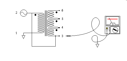
It should be obvious by now that terminals 2, and 3, are in fact the
same terminal, as configured above, I just thought I'd mention that, if this
didn't automatically occur to you, it should have, you've missed something
critical along the way, go back and review some of the early lessons.
Anyway Terminal 3 should be 120 volts with respect to ground,
your line voltage may not be exactly 120 so don't fret if it's within 10%.
Terminal 4 should be higher by the voltage of the first secondary,
terminal 5 should be higher by the voltage of the second secondary,
and finally terminal 6 should be still higher by the voltage of the
third secondary. If your transformer has one of the windings reversed you can
fix it, and go on. Once you get them all in phase, that is so that they all
add, power the whole thing down, leaving the wires of the transformer windings
connected to each other, and carry the transformer to the workarea where you
intend to mark the wires.
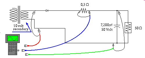
Next I show a simple Half Wave rectifier, and simple single capacitor filter
circuit, with some provision for measuring the current waveform, carried by
the diode. What is ofcourse being measured is voltage drop across the
0.3 ohm current sensing shunt resistor. The following frame I show
actual waveforms taken by the Velleman K7105 handheld oscilloscope. Notice
how, as the current waveform reaches maximum, the input voltage delivered
by the transformer, shown here in Red is severely flattened by the nonlinear
current drawn by the diode, and then on the negative half cycle, the
transformer, nolonger subjected to the diode's load, is free to produce
almost two more volts. Also observe how, as the Red positive peak forward
biases the diode, only as it exceeds the cap voltage by the diode drop,
does any energy get transferred to the cap to replenish its charge. This is
by contrast a very brief period of time, this time slice is so short, that
to accomplish the charge replenishment, almost 1 1/4 amps flow
in that brief period of time, into a cap, that is only providing
240 milliamps of current to the load. Rectifier diodes are routinely
subjected to very high repetitive pulses of current, many times the design
load current. Any series resistance, in either the cap, or the transformer
has considerable impact on the amount of power such a power supply can
deliver.
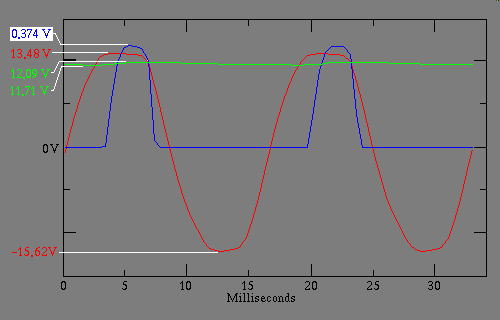
Both the Red transformer voltage waveform, and the Green capacitor voltage
waveform are measured at the same scale setting, the Blue current waveform,
is in reality a tiny voltage measured across a current shunt, and would
therefore be inappropriate to set at such an insensitive scale setting.
All of these however are referenced to the same zero reference
to make easier the interpretation of this first waveform on the part of the
student. Notice that the Green capacitor waveform has so little activity
that much of the detail is lost. In the next set of waveforms I suppress the
zero and rescale the Green capacitor waveform when I cover Full wave
rectification, because without this technique the 'Y' axis movement is
a mere single pixel. I mention this here so as to warn you not to be
complacent about zero suppression.
These are real waveforms, not textbook drawings, and some unanticipated
phenomena needs perhaps an educated guess as to the causes. First you would
expect that the capacitor voltage waveform would follow the transformer
output into the circuit by 7 tenths of a volt, but it follows by more
like a volt and a half, why? These voltage measurements were made one at a
time, and then pasted together into a composite, it is possible that the
powerline voltage fluctuated a little, or I may have absent mindedly made
the measurement with the current sense resistor still in the circuit while
I made the measurement, but even including that 0.374 volts still
fails to account for the discrepancy, so I say a combination of factors,
wire resistance of the cheap "Radio Shack" clip leads, line voltage
fluctuations between measurements, and measuring cap voltage while the
current shunt was still in circuit all came together to produce this
anomaly.
Another anomaly is the fact that the bottom half cycle, of the Red
transformer output voltage is not as round as it seems it should be
I assume this is some of the compound saturation effects of the test
setup I used, an isolation transformer drives a Variac, it drives the
transformer shown, which is exhibiting a slightly less than sinusoidal
negative half cycle.
Third I need to mention that all of these waveforms were phased, that is
aligned to each other with respect to time after the measurements were
taken, in the Grace math package, using Emacs macros to do the alignment.
I hope I got them right :-)
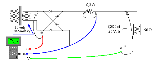
Ok on to the Full wave rectifier circuit.
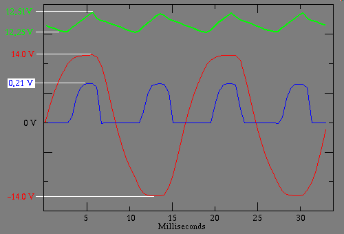
Like I told you, the Green cap voltage waveform is zero suppressed
this gives me a way to provide you more detail than would otherwise be
possible. Notice that the Blue current waveform is only a little more than
half the magnitude, of its Half Wave counterpart, still delivering the same
output. This happens because it occurs twice as often, if you missed this,
study the two waveform sets, comparing them to each other. Showing the Green
current waveform in this kind of detail, allows you to see why they call
this sort of waveform a Ripple Wave, again the short rise time
that is the charge cycle, is in contrast to the relatively slow fall, or
discharge time. RC Time Constants describe the discharge portion
of the wave, and therefore the magnitude of the ripple. In normal powersupply
design you want as little ripple as possible, on the other hand an infinitely
large cap is also infinitely expensive, and infinitely heavy. not to
mention large as the universe. So you have to make some tradeoffs.
Also the smaller your ripple voltage, the more severe the exaggeration of
the diode doing all the work in an ever thiner sliver of time.
The information I've given you concerning time constants, RC discharge
characteristics, and the like is all that you really need to design such
powersupplies to a second approximation. There are formulas for many standard
configurations, you might be tempted to acquire some of them, but you
really don't need them, and few who memorize them remember them ten years on.
So I don't make a big deal about them, the Internet is vast, if you think
I should drop some pointers, drop me a line, and I'll consider it.
Analog series pass transistor based regulators present a
Constant Current load to the filter cap, and switch mode
regulators present a Constant Power load to the filter cap.
These various types of load make very little difference to the curve,
or the way you calculate the size of the cap if your ripple is small, eg.
less than ten percent. My first approximation treats the load as if it
were a constant current, and usually that's all that's necessary. Line noise,
variations in temperature, and component tolerances, all factor in to cause
far greater error than the miniscule error caused by using the wrong
current curve model. So the first approximation Rule of thumb
is to simply use the relationship of one Ampere of discharge current, flowing
out of a one Farad cap, steadily reduces its voltage by one Volt per Second.
To keep the proportions straight in your mind reducing the discharge current
slows the voltage decent, and reducing the capacitance speeds up the voltage
decent, in linear proportion.
Some texts take up weeks of your time on the above subject, and when you
try to apply all the theory in the lab you discover the fine points the
theory makes can't even be measured because of all the
noise factors. I have given you a simple practical way to
compute the size of the cap that's hard to beat. I'm not discouraging
you if you want to know the details, as I said before the Internet is a
big place, go for it.
Some interesting rectifier configurations:
At this point I will assume you've tried a few of the things I've put forth
as experiments, the next section will detail some arrangements of diodes,
and capacitors, that produce useful unregulated DC power supplies.
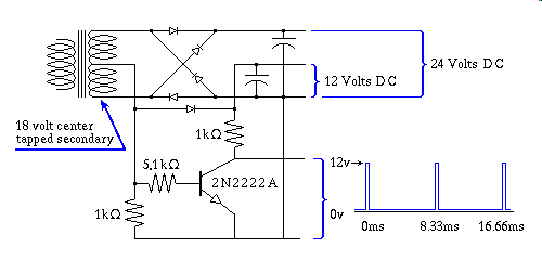
The above power supply produces two voltages from the same transformer, plus
a handy full wave signal that can be used for detecting Zero Cross. Both of
the DC voltages, are full wave rectified sine waves fed into the filter
cap and as such require considerably less filtration, eg. capacitance.
The bottom half conditions the signal into a short pulse for timing things
that rely on things that coincide with the 60 hz beat of the powerline, a
very precise timebase.
To understand how this circuit works, momentarily ignore the top two diodes
and, the cap that they charge, also ignore everything below the bottom diode.
What you have left is a simple two diode full wave rectifier, that has a
seemingly useless, but relatively harmless third diode, the bottom one,
charging the cap that drives the 12 volt supply. Now add in the resistors
and transistor, and the significance of that third diode suddenly has
relevance. That third diode blocks the charge on the cap, from propping up
the voltage across the bottom resistor during the period when the
AC sinusoid is not at maximum, thus the bottom resistor has a textbook
picturesque full wave rectified sinewave across it. The middle resistor
converts this waveform into current that drives the base of the transistor
and since the transistor's beta factor, a measure of it's current
amplification capability is on the order of 100, and since the transistor's
base emitter junction, behaves like a diode, the emitter is the bottom
terminal in this drawing, the transistor is biased on for all of the
wave, except for the brief moment of time that the AC sinewave crosses
over the zero line. The top resistor tries always to hold the output voltage
at the transistor's collector terminal to the 12 volts that is always
available at the cap when the circuit is powered, but since the transistor
is on most of the wave, like a switch that is closed, the transistor
wins this fight, and holds the voltage very close to ground potential,
most of the time. The exception is ofcourse during zero cross, when the
transistor's input base terminal current falls to zero. For that brief moment
in time, the transistor switches off, and the collector voltage, at
the whim of the top resistor, is pulled up to 12 volts DC
for that brief interval.
Now add in the top two diodes to complete the picture, and what you have
there is simply a full wave bridge rectifier driven from an
18 volt RMS transformer secondary, whose peek voltage 25.45 charges
the top cap to about 24 volts, after you factor in diode drop. Loading
this powersupply to obtain useful amounts of current will pull down the
output voltages to somewhere between 11, and 10 on the bottom cap,
and 22, and 20 on the top one, depending on the applied load.
Such is the case of any unloaded, unregulated powersupply. It's far from a
perfect world, but even without true regulation one can make it much better.
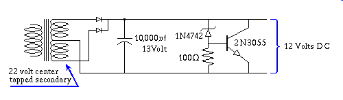
The right half of above circuit is what is known as a
shunt regulator. The 22 volt RMS center tapped
secondary will charge an unloaded cap to 14.85 volt assuming a
0.7 volt diode drop, kind'a high for some 12 volt devices, and
considering powerline fluctuations this can be even worse, but even light
loading can pull this voltage down considerably, such that under normal load
this powersupply is right at 12 volts. The trouble is, that the unloaded
cap has almost 15 volts with quite a bit of current behind it, for
atleast a few milliseconds, and solidstate devices can be destroyed when
subjected beyond stress limits for as little as a millisecond. What the
circuit on the right does, is to, in the absents of any load, provide a
small, but adequate load, enough to clamp the voltage across the cap
to 12 volts + 1 diode drop, in this case the base emitter
junction of the 2N3055 has the nominal seven tenths diode drop, and the 1N4742
is a 12 volt Zener Diode, a diode precisely spec'd for its Reverse
Breakdown potential, in this case 12 volts.
The good, and the bad:
I don't really think of a shunt regulator, as any kind of a true regulator.
What they do is limit the unrestrained overshoot, in other words they make
great surge protectors. In the absents of any load the
shunt regulator is working at it's hardest, to drain off excess
voltage, but as soon as the load is switched on, the load pulls power away
from the powersupply, causing it's voltage to droop, and now the
shunt regulator is effectively removed from the circuit, until
such time that the load is switched off. Such a scheme makes optimal use of
the powersupply's output under load conditions, but in a noload situation
it also wastes about a watt of power. This circuit provides a
hard clamp meaning it is very responsive to spikes, due to the
fact that it is usually partially on, that is the 2N3055 is usually partially
conducting, and thus more ready to respond to variations in voltage.
Placing a carefully chosen resistor across the Zener diode can trickle just
enough current even at load conditions to insure this added responsiveness.
1300 ohms might be a good starting point for such a resistor, and if
it were a pot, you can tune for minimum smoke :-) the idea here is not to
alter the functionality of the circuit as a whole, rather you adjust the
pot to the point where it just bearly begins to affect the unloaded voltage,
and then back off just a smidgen.
I show the circuit being powered by a 22 volt center tapped
secondary followed by two diodes, another viable configuration is to use
a 12 volt non-tapped secondary, and a four diode full wave bridge
rectifier to feed the cap, this is roughly equivalent, inspite of the
somewhat higher voltage, eg. a 22 volt center tapped winding
develops a peak voltage of 15.55 on each leg and has one diode drop, where
as a 12 volt secondary produces a peak voltage of 16.97, and has two
diode drops in a full bridge rectifier. To contrast the unloaded theoretical
voltages of these two schemes, we get 15.57 volts for the 12 volt
bridge rect version, and 14.85 volts for the center tapped
22 volt version. Only about a diode drop of difference between the two
schemes, thus if you were real particular, you could add an additional
diode to the 12 volt non-tapped version if you really wanted it to
behave identically to its 22 VCT counterpart.
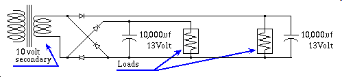
In the above circuit I show a clever configuration, of an almost, but not
quite, full wave bridge rectifier. This modification of a bridge rect.
provides two independent loads, that operate in the same polarity, power
that has nearly zero interaction from the neighboring load. In other words
if one load's current fluctuates, as a result of circuits switching on and
off, the voltage of the other load remains steady. This is not the quite the
same thing as regulation, if the AC line voltages fluctuates, both supplies
are affected. Often you are designing circuits that have very sensitive
amplifiers in one section, that control massive amounts of power elsewhere
in the circuit, it can be an incredibly daunting task to keep power
perturbations in the output stages, from causing the sensitive input stages
to react to them, thus causing a feedback loop that oscillates at the
total loop delay period. The way this circuit works is it charges one cap
on the positive half cycle of the transformer, and the other cap on the
negative half cycle. On the down side, both power supplies, in achieving
independence from each other, are no longer full wave rectified, they are
only half wave rectified, thus they require much larger caps to achieve
proper filtration.
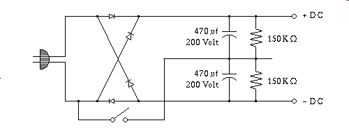
This non-isolated powersupply has a switch at the bottom that changes the
voltage produced by the supply. Plugged into 120 volts, with the switch
open the diode bridge rectifies the AC voltage and places the result across
the two series capacitors, the resistors are there to insure the voltage
across the two is equal. Measured from the minus DC to the plus DC you would
read about 170 volts, no surprise, Ok now close the switch, suddenly the
output voltage jumps to double, 340 volts! Why? The switch bypasses
the two diodes it is directly connected to, changing the circuit from a
fullwave rectifier bridge, to two DC halfwave powersupplies wired in series
in additive fashion. In the configuration with the switch closed, the
the only two diodes that have any effect are the top diode, and the second
from the bottom, the others remain reverse biased at all times. While this
is a pretty slick circuit, a clever way to get two different voltages out
of the same supply, that is not how it is used. The voltage selector switch
on the back of your computer's powersupply is wired exactly the same way.
It is set switched open, for operation on an electrical outlet that delivers
240 volts AC, and it is switched to the closed position for
operation on 120 volts AC service, thus making it capable of
operating on both domestic, and foreign electric service, and assuming the
switch is set properly, it delivers the same DC voltage to the electronics
in either case.
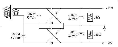
Here's a way to arrive at a pair of plus, and minus fullwave rectified DC
powersupplies, where the negative supply, in this case, is not required
to deliver very much current. The two 200uf caps to the left of the diode
bridges are employed to shift the AC sine wave by an offset equal to the
peak voltage of that sine wave, thus still applying AC voltage to the
bottom diode bridge, but shifted negative by the peak voltage value of
that AC input voltage. This trick makes the input power entering the lower
diode bridge appear almost as if it were coming from an isolated
winding of the transformer, even though the transformer only has a single
secondary winding. This kind of a powersupply is very common in external
modems that are powered by a wall-wart with an AC output, usually
12 volts AC. The modem needs the plus, and minus supply voltages
to be able to generate the plus, and minus 12 volt signals required
by the RS232 serial signal standard that is carried by the 25 pin
data connector on the back of such a modem. To further emphasize this
technique of using the two caps on the left as a kind of DC isolator, I
show below a version of it with a battery demonstrating the flexibility
of such a design.
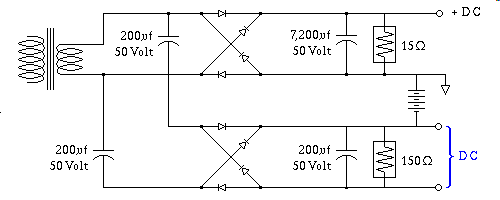
The battery in the above circuit, could be any DC power source, simply shows
how, by capacitively coupling the ground referenced secondaries AC signal
into the DC floating lower diode bridge it now forms a separate powersupply
in it's own right, floating, in this case, on top of a negative battery
voltage. So you might ask, what if you put in an extra diode bridge, and
a couple of diode isolator caps, like the ones on the left, and another
filter like the one on the right, to replace the battery with, it seems
like you would get a total negative voltage measured from the top, to the
bottom most terminal on the right, of three times the peak voltage, kind'a
like getting something for nothing ain't it? Well yes, and yes it would do
exactly that, but all three power supplies would draw a version of their
respective currents from the transformer. This gets us into the next
subject, namely Voltage Doublers.
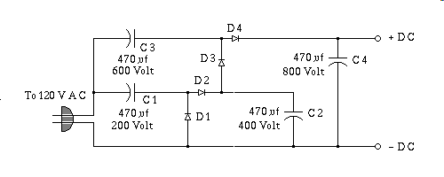
Measured from the minus DC to the plus DC you would read about 680 volts
To understand this circuit one needs to cover how it works in stages, first
some reference points. Notice that the minus DC terminal is, if the power
plug were polarized appropriately, at, or near earth ground potential.
This fact would never be considered safe, but all hot chassis
systems take this sort of thing into consideration, in much the same way
as the light socket screw threads, being more exposed, are always connected
to the neutral, eg. white wire. In my discussion of this circuit, all
voltages, unless otherwise stated will be referenced to the
minus DC terminal. To explain how this works, I will describe,
each of four half cycles separately, one at a time, beginning with the
line power input, the hot side of the power plug, starting at zero, and
headed downward on a negative half cycle. Temporarily ignore everything but
the C1, and D1, as the input voltage reaches its negative peak, C1 is
charged to 170 volts. Now for purposes of understanding this circuit
I want you to suspend what you know about physics for a moment, and pretend
that C1 is now a 170 volt battery of infinite capacity, and zero
impedance, or resistance. As the input line voltage rollercoaster rides
from the bottom troff, eg. negative peak of the sine wave, back to zero,
C1 acting as a battery, now dumps its 170 volts into C2 charging it
to 170 volts, but as the input line voltage rollercoaster rides up to
the positive peak, as it rounds the top, C2 now has a potential of
340 volts, and cycle after cycle keep biasing the diodes forward on
the peaks of the waves, just enough maintain C2 at 340 volts. So now
for purposes of understanding I want you to think of C2 as a battery charged
to 340 volts from here on out. I now want you to think about what is
happening to C3 when the the hot side of the power plug, is starting at zero,
and is about to head downward on another negative half cycle. At zero volts
on the hot side of the plug, C3's negative terminal is effectively connected
to ground. C2 is charged up to 340 volts, and that 340 volt
potential is carried by D3 also charging C3 to 340 volts, this when
the input line voltage is at rest, eg. zero volts. As the roller coaster
ride continues and the hot side of the powerline sweeps down to the negative
peak of the wave, it further charges C3 by an additional 170 volts to
a total of 510 volts just as it reaches the bottom of the wave. Once
again I want you to think of C3 at this point as a 510 volt battery.
As the input line voltage rollercoaster rides from the bottom troff, eg.
negative peak of the sine wave, back to zero, C3 acting as a battery, now
dumps its 510 volts into C4 charging it to 510 volts, but as the
input line voltage rollercoaster ride continues up to the positive peak,
as it rounds the top, C4 now has the additional positive peak value of
the line voltage potential 170 volts, added to C3's 510 volts,
charging C4 to a whopping 680 volts, and cycle after cycle keep biasing
the diodes forward on the peaks of the waves, just enough keep C4 at
680 volts, even with loading applied.
If it's negative voltage you want, swap the polarity of all the components,
and presto, instant Negative Voltage Doubler, and ofcourse
wiring two of them side by side one negative, and one positive, yields
a plus, and minus powersupply, in which the combined voltage of both, can
be obtained across the plus to minus DC terminals, for example if you made
up two copies of these things, using my two stage example above, and the
second copy was a negative Voltage Doubler the output from
the minus DC to the plus DC would be one thousand three hundred sixty volts!
Do you see why I call this site Zap Tek
I have shown a two stage Voltage Doubler in this example, more
stages, can be added if you want even more voltage, or you could just as
well have stopped at one stage, if your needs would have been satisfied
with only one stage. The trouble with doing this, using the above circuit,
is the difficulty in finding suitably high enough voltage capacitors, after
you get beyond two or three stages, a mere four stages and you're looking
for capacitors with a working voltage of over a thousand volts, these are
both rare, and needlessly expensive. The above circuit while simple to
conceptualize, is far from optimal, I show below a slight modification of
the hook up, that allows you to cascade dozens of these stages together,
using only 200, and 400 volt capacitors.
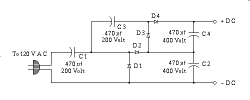
Something to bear in mind about ridiculously large arrays of
Voltage Doublers, wired as above, to optimize for
inexpensive, more easily obtainable capacitors. Unlike the previous
easily comprehended non optimized version, in the optimized
circuit circuit shown above each successive stage adds its current
requirements to the previous ones load, so in a really large array of
these circuits the one nearest the ground carries all the current of
all of them above it, AND every new Voltage Doubler
added to the end of the array, combines it's AC load with all of the
others below it such that the impedance of C1, and therefore its
capacitance must be high enough to effectively carry the combined
current of all of them. Similarly, C2, C4, and all the rest of the
even numbered caps in the entire array are all effectively
wired in series, so their capacitance follows the rule of series
capacitance, covered earlier in this course.
I must admit to seeing large arrays of these in production. Two cases I
know of where this was done, a Laser powersupply I've seen had about
twenty stages of these things, cascaded together to form the five to six
thousand volt excitation voltage for a low cost line powered HeNe Laser,
and the technique was also employed to develop the second anode voltage
of early, non-flyback design Oscilloscopes. If you do build a large array
of these, be careful of placement of components, and insulators, a mere
ten thousand volts will jump a gap of up to an inch under some conditions.
If a spark does jump, shut off the power, and to avoid having to rewire
everything, invest in some GC Electronics "Corona Dope"
apply the stuff liberally around the area that is sparking, and allow it
to completely dry before energizing the circuit, the volatile vapors,
are flammable, and if a spark should jump in the presents of these vapors
your circuit may catch fire.
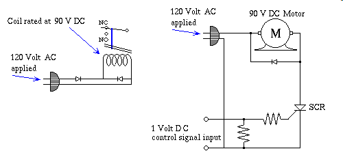
There is a standard for 90 Volts DC. Devices that use this voltage
are inductive things like Relays, and Motors. As far as I can tell the power
source these things were originally intended to operate with was halfwave
rectified 120 Volts AC, with a back diode to retain current within
the inductor during the other half cycle. If you operate most of these
devices on 90 Volts DC, and measure their coil current, and then
once again connected up as shown above on the left, the currents will be
within a few percent of each other. As for the circuit on the right, it is
only an example of a practical use of this concept. Of all of the experiments
contained in this page, lesson 014, I expect you to try them all out if
you possibly can, save one, the one above on the right hand side.
It deals with an SCR, eg. Silicon Controlled Rectifier
used as a 90 volt DC motor control device. It would be jumping
the gun indeed to expect you to wire that one up, considering I've barely
touched on transistors, as switches, and current gain devices, SCRs are
complex devices comparatively speaking, and have as one of their inherent
characteristics, a kind of Memory of their switched state. The only
reason I placed the circuit here is to show a practical application of
halfwave, rectification driving an inductive load, with a back diode to
retain the coil current during the Off cycle. To elaborate just a
little, the motor will switch on and run full speed with the voltage of a
single flashlight battery applied to the input terminals of the circuit,
and speed control of the motor can be achieved by driving the input with
a carefully prepared, critically timed series of one volt pulses, directed
to the same pair of input terminals.
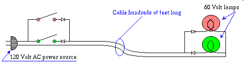
The last two experiments are what I consider novelties, in the circuit above
use 1N4003 diodes, and although 60 volt lamps are optimum, in that a
60 volt lamp will light up full brilliance in this circuit, you can
for the purposes of experimentation use standard 15 Watt 120 volt
light bulbs, they just won't light as brightly. Incidentally the 1N4003 diodes
will handle 1.0 Amp so the circuit will handle a 100 Watt bulb with
ease. Ok after you wire it up, play with the switches, you'll find that
the Red lamp, responds to the Red switch, and the Green lamp responds to the
Green switch. They are completely independent of one another. Yet they do
this over two wires, how is this possible? To find out, trace all circuit
paths, for both half cycles of the incoming AC power.
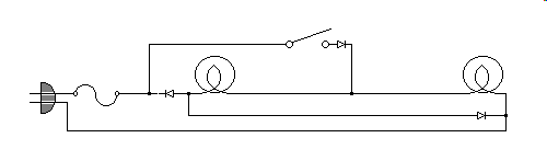
I have two 8" by 8" by 3" Glass blocks setting on my desk, it's an ordinary
desk, I got when a warehouse was throwing out perfectly good usable stuff,
this desk was one of the things they threw out. This desk is what I use for
the bulk of my computing, although since I don't do bleeding edge, my
computers are all over the house, forming a large LAN, large that is for
a home. Most of them are refugees like the desk, low end Pentiums
that I picked up for $10.00 typically. Across the top of the two glass blocks
rests a pine plank, that serves as a shelf for the 14" SVGA monitor that I
got for asking if I could have it, seeing as how it's fate would have been
otherwise intertwined with a landfill somewhere. The under side of the pine
plank, directly behind each of the glass blocks, are one for each, two
60 watt clear lightbulbs, the bulbs you see in the diagram above.
Also mounted on the underside of the pine plank is a plastic project box
with a long handled toggle switch protruding out the front, just beneath
the monitor. That toggle switch is also the one in the diagram. What this
circuit does is rather interesting, I will describe it viewing the bottom
wire as the ground return, and the prong on the plug, that is connected to
the fuse I will refer to as the input voltage, lamp 1 is the left lamp,
and the other one is lamp 2.
Ok here we go, first the switch open case. When the input is positive, no
current flows, when it is negative, that half cycle the two lamps are wired
in series across the 120 volts. Thus with the switch open, the bulbs
are wired in series, and are powered up for only half the cycle. This
results in only one quarter of the available power that would ordinarily
light the lamp.
Now the switch closed case. When the input is positive the left diode is
reverse biased, the middle one is forward biased, and lights lamp 2.
It also feeds current through lamp 1 via the right hand diode, thus
lighting lamp 2, so for the positive half cycle, both lamps are wired
in parallel. And during the negative half cycle they behave as they did
in the switch open case. Thus with the switch closed, one half cycle is
spent lighting them in parallel, and the other is spent lighting them
as if they were wired in series. One half plus one quarter equals three
quarter, so with the switch closed they light as if they are powered with
3/4 of their wattage. Throw the switch one way, open, and they serve as a
night light, and throw the switch to the right they serve as ancillary
lighting for the otherwise dark shadow that my pine plank would cast on
the desk. If you looked at my internal link
about Lamp Life formulas
you would know what running a lamp at three quarters of it's rated power
does to the life of the bulb, basically they never burn out, they just run
and run, and run some more. The only time they ever do go bad, is when
I do something like change the Glass Block, or move the shelf, then
vibration, gets'em, the mechanical shock of moving things around is just
more than a filament that's been given the softest life possible, for
years on end can stand, and usually when I move the shelf I have to replace
both lamps, due to mechanical shock.
Summary
I've given you about twenty low cost experiments, involving simple diode
circuits, simple in that the demands of the diodes in these experiments
are, for the most part, first approximation Rectifier Diode Applications
that require only that the diode behave as a simple one way
conductor of electricity. I've also given you a myriad of construction
techniques along the way, with any luck you've improved, if they were
absent, your soldering techniques, and hopefully took a gander at
my tool abuse page
for even more techniques. By now you should have some idea of what use an
Oscilloscope is, and maybe are considering obtaining one, if it can be
purchased inexpensively. Some people spend enormous sums of money, only to
discover electronics is not their cup of tea, the Scope sits around the
house for a few years, and then in a delirious moment of
Spring Cleaning a Garage Sale happens, if you are there,
you must understand that pressure from their Significant Other, often of
a background that has no interest in electronics, sees such a valuable
piece of gear as little more than an eye sore. Their loss, is
your gain, this is your lucky day.
Every one of these experiments demonstrates something interesting, and unless
you already have electronics down cold, you need to wire them up, and try
them out. I don't see how you can get this stuff by reading about it, the
reason I say this is that the thing that teaches isn't the text of my web
site, or a book, it's the seeming failures you encounter when you attempt
the experiments. The failures you encounter require you to re-examine
those comfortable, but incorrect assertions you've made while reading
about the subject. The revisions you make to your thinking, in the
endeavor to solve the puzzle that is causing the experiment to fail, are
the revisions that actually teach you any discipline, and this is
especially true of electronics.
Back to Learn Electronics
Next
The large print Giveth, and the small print Taketh away
CopyLeft License
Copyright © 2000 Jim Phillips
Know then: You have certain rights to the source data,
and distribution there of, under a CopyLeft License