If the two animated pictures 5th, and 6th frame appear frozen, or freeze up after running a little bit, try moving the mouse, or pressing the shift key by itself. Failing that, I provide a way to download these two files, so that you can see what they look like, using an appropriate viewer, not the browser, on your machine. Some people have reported that too many simultaneous animations on older ones fail at the first frame, so you might try them one at a time, if you're having difficulty. Also some older browsers cough when more than one animation is presented on the same page, and they get real sluggish.
Your Notes:
-------------------------------------------
Here are the two formulas I used in the
first picture. Coil formulas are more
difficult to come by, and less precise
and while a capacitors dielectric
constant is fairly uniform, a coils
permeable core is not as predictable due
to a variety of factors like saturation
temperature effects, and so forth, the
exception is an air core inductor.


            D A (N - 1)
C = 0.0885 -------------
                  S
Where:
C = Capacitance in Picofarads
D = Dielectric constant
A = Area in square centimeters
N = Number of plates
S = Spacing between plates in cm


     0.8 ((N A)^2)
L = ---------------
     6A + 9B + 10C
Where:
L = Approximate Inductance in Microhenrys
    Approximate here means to within 1%
N = Number of turns of wire
A = The mean radius in inches
B = The length of the coil in inches
C = The depth of the coil in inches

-------------------------------------------
Beyond those two equations I give you some
variations on calculating inductance of air
core coils. Here's one that computes a
single layer coil, wrap wire one layer deep
without overlapping any windings

      (N  A)^2
L = ------------
     9A  +  10B
Where:
L = Approximate Inductance in Microhenrys
    Approximate here means to within 1%
N = Number of turns of wire
A = The mean radius in inches
B = The length of the coil in inches


This is a metric version of the single
layer coil inductance formula.
It only applies to very long coils

     (4 (Pi^2)) 10^7 N^2 R^2
L = --------------------------
                S
Where:
L = Inductance in Henrys
N = Number of turns of wire
R = The mean radius in meters
S = The length of the coil in meters

To handle short coils you multiply the
above equation by a coefficient "k" taken
from a graph, this was in the McGraw-hill
Standard Handbook For Electrical Engineers
Not a very practical way to compute "L"


Here's the formula for the coil I used in
the first picture, modified to work in
metric units. Since the original formula
was only an approximation, eg. 1 percent
the resulting formula is also only an
approximation, but hand wound coils are
seldom measured with caliper micrometers,
so an approximation is probably all you
will ever need.

      0.8 x 10^-6 x N^2 x 39.37^2 x R^2
L = --------------------------------------
   (6x39.37xR) + (9x39.37xB) + (10x39.37xC)

And now I multiply out the constant terms:

        .00124  x  N^2  x  R^2
L = ------------------------------------
     (236 x R) + (354 x B) + (393 x C)

Where:
L = Approximate Inductance in Henrys
N = Number of turns of wire
R = The mean radius in meters
B = The length of the coil in meters
C = The depth of the coil in meters

Here's something to ponder:
Through out these equations you've noticed
in the metric versions the term (4 (Pi^2))
which evaluates to 39.4784 and the meter
is   defined,  as  39.37  inches  exactly.
These two numbers vary by only one quarter
of one percent. I did not make these types
of conversions in my algebra, but an author
I have plagiarized may have, so be advised.
I do endeavor to make these things right
but many of my books are rather dated, if
you can point me to a definitive site, it
would be very much appreciated, by me, and
others will benefit as well, thanks.
-------------------------------------------

To find charge stored in a capacitor

Q = C x E

To find energy stored in a capacitor

     C x E^2
U = ---------
        2

To find Volt-seconds "charge" *  stored in
an inductor

Vs = L x I

To find energy stored in an inductor

     L x I^2
U = ---------
        2

Where:

U  = Energy in Joules
   = One watt delivered for one second

C  = Capacitance in Farads

L  = Inductance in henrys

E  = Voltage in volts

Q  = Charge in coulombs

Vs = Volt Seconds...
* while not really "charge" the analogy is
often useful to think of voltage as
charging or discharging an inductor.
A Coulomb is merely a quantity of electrons "trapped" in a system that
are available for the production of future energy, that is, under the
right circumstances they could become energy, but they by themselves
are not PE, Potential Energy, to be quantifiable potential energy, we must
know the Capacitor's capacitance they are being harbored in, this fact is
mentioned by some of the more complete electronic textbooks.
Now for a leap of logic:
An inductor can also be a harbor for disembodied electricity, and it's stated
inductance can, be used to quantify PE. Although a capacitor uses a different
method of storing PE, namely electric fields built up in the dielectric layer,
in an inductor, magnetic fields are the method employed. In my discussion of
this I assume "ideal" devices in the following two examples:
First the capacitor, apply a constant current of one ampere, for exactly one
second, to a one farad capacitor, and open the circuit. It's open terminal
voltage will be one volt, assuming it started at zero. It has one coulomb of
charge simply collected around it's plates, and holds one half Joule of
potential energy.
Now the inductor, apply a constant voltage of one volt, for exactly
one second, to a one henry inductor, immediately short the inductor,
subsequently removing the voltage source. One ampere of current now flows
endlessly circulating through the inductor, and its perfect short, we are
still assuming no loss. In this static state, it does no work, the inductor
is merely harboring electricity, just as the capacitor did! And like the
capacitor the inductor also holds one half Joule of potential energy.
The difference here is, what is stored Volt-seconds, and how it's stored,
namely non-permanent magnetic fields that would normally collapse, if not for
the presents of the short across the inductor. It isn't that these magnetic
fields aren't trying to collapse, they are, but their effort to collapse
creates electromotive force, in a circuit, of, in this idealized example,
Zero Ohms, thus the one ampere of current is maintained, and that one ampere
maintains the "pumped up" magnetic field equilibrium.
To extract the half Joule of potential energy from the capacitor one could
close the circuit with a resistance. Because the coulomb of charge is
manifested by the capacitor as a depleting voltage, if a one ohm resistor
were connected to the capacitor, an RC discharge starting out at one
ampere (one volt divided by one ohm) tapering to an asymptote of zero would
be the result.
To extract the half Joule of potential energy from the inductor one could
open the short across the inductor to allow a resistance also previously
connected across the inductor to receive any energy the inductor had to offer.
This energy is initially presented to the resistor as a constant current
source of one ampere, but tapers to an asymptote of zero as the voltage
is expressed, as current flowing through a resistor will do. The resistor
will drop one volt initially, the one amp held in the inductor multiplied by
the one ohm of the resistor, but the inductor is attempting to be a current
source, not a voltage source, voltage is expressed as drop across the
resistor, and that voltage is a function of the resistor's ohmic value.
Indeed if you were to open the circuit, without the resistor in place, the
inductor would try to place one amp of current through a resistance of
infinity ohms, when you multiply one times infinity, you get infinite voltage,
in this idealized example. In practice, the imperfect inductor shorts out
internally, if necessary, by ionizing the air around the windings of the coil,
and forming a spark, that dances across the windings themselves. In other
words, real inductors, will provide their own resistive load, by self
destructing if necessary, to dissipate the Joule of energy.
The capacitor analog of this, is that if a capacitor is suddenly shorted,
one volt in this case, placed across as nearly to zero ohms as you can get
and still be positive, results in nearly infinite current initially.
Why don't I just say Zero Ohms? The reason is that any number divided by
zero is undefined in mathematics. The foundation of Calculus, rests on a
subject called Limits, that finds ways to work with numbers that do things
like division by zero, but this course does not require high math, only that
you need to know what high math does for electronics.
In the old days, the "Pre Pocket Calculator" days, electronic technicians
memorized the five "Time Constant" values, they are... 36.7% 13.5% 4.97%
1.83% and 0.674% Knowing these will most often solve for "Time" required to
charge a capacitor to voltage "X", or inductor to current "X" problems that
technicians are likely to encounter. Another factoid to add to this, and
probably more useful, is the notion that a capacitor/inductor reaches 50% of
it's charge at 0.7 time constants. This is only a nice round number, the actual
number is 0.693147181, obtained from my pocket calculator Ln(x), where "x" is
the reciprocal of 50% Note: for those of you not grounded in the notation,
Ln(x) refers to the Natural Log of "x" read your scientific calculators owners
manual for details of how to make this calculation, if done right your result
should agree with the number stated here.
-------------------------------------------
The five "Time Constant" values, are just
a shorthand used widely in the electronics
industry, I list the values in tabular form
below for easy integration into your notes.

36.7%            *


                  .


                    .


13.5%                  *

                          .

4.97%                        *

1.83%                              *
0.674%                                   *
          0Tc   1Tc   2Tc   3Tc   4Tc   5Tc


         1
Vd = ---------- Vi
          (Tc)
         e

         1
Id = ---------- Ii
          (Tc)
         e

Where:
Vd = Discharge Voltage
Vi = Initial Voltage (voltage at 0 Tc)
Id = Inductor Current flowing after a given
     time interval has elapsed
Ii = Initial Inductor Current (I at 0 Tc)
Tc = Time constant

Tc for a capacitor = (T x R x C)

   or for the case of the inductor
      T x L
Tc = -------
        R

 T = Time in seconds
 R = Resistance in ohms
 C = Capacitance in Farads
 L = Inductance in Henrys


Alternatively because any number raised to
a negative power is the same as the
reciprocal of that number raised to that
positive power, the two expressions above
can be represented as the following


      /    (-Tc)  \
Vd = |   e         | x Vi
      \           /


      /    (-Tc)  \
Id = |   e         | x Ii
      \           /

The Big Picture:
Think of electric voltage, by way of analogy to the laws of motion and
inertia as being physical speed, and electric current
is in this analogy, likened to physical force. I will elaborate.
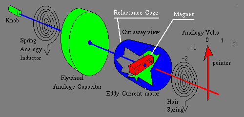
Imagine a shaft, with infinitely smooth bearings, eg. no friction to interfere
with the forces we will apply to it. The shaft may be rotated, freely, perhaps
you have attached a knob, with a speedometer, to this shaft, a speedometer,
the kind of device in the dash board of your automobile, is a relatively
simple device, that has a cable connected to the drive train, usually a nylon
gear is meshed, to a lead screw inside the transmission, or in the case of
a Volks Wagon, they "jack in" to the left front wheel, as the wheel rotates,
so too does the center of the cable, and ultimately a permanent magnet,
attached to the end of the cable, inside the speedometer. Suspended around
the magnet, but not touching it, is a non-magnetic, electrically conductive,
thin, cylindrical shroud, that serves as an "eddy current motor" sometimes
referred to as a reluctance cage, and the whole mechanism is sometimes called
a magnetic reluctance motor, is fastened to a shaft, with a pointer, and
a spring. The faster the cable rotates, the more eddy currents in the shroud
are generated, these translate into mechanical force, and the spring allows
the pointer needle, to deflect linearly with that force, according to Hooks
Law. I digress, if you obtain a small but high power rare earth magnet, and
drop it through a piece of copper tubing, about three foot long, it can
take as long as fifteen seconds to traverse the copper tube acted on by
gravity. As the magnet falls through the tube its magnetic field causes
current to flow in the copper tubing. But the copper tubing is circular, and
therefore appears as an electrical short circuit. The current in this ring
of copper creates a magnetic field of its own, and that field tries to
stop the magnet. But as time proceeds the copper is not a perfect conductor
and the current fades away, as it is converted to a miniscule amount of heat,
allowing the magnet to move a little more. The magnets motion once again sets
up more currents in the copper tubing, and the cycle repeats. The gradation
of overlapping phenomena, makes the process uniform and continuous. This
is not anything like mechanical friction. Friction exhibits a strange
nonlinear characteristic as traction breaks free. Magnetic reluctance is,
in this analogy, the mechanical analog to electrical conductance, and the
reciprocal of magnetic reluctance, is the analog to electrical resistance.
Anyway back to analogy. For the purposes of this analogy I will
modify the speedometer so that the spring is calibrated to point the pointer
when at rest, to center scale, so that I can see both forward, and backward
speed represented on the dial, and ofcourse I'll redraw all of the markings
on the dial, so that when the speedometer is at rest, it points straight up
to zero eg. half scale, and markings to the left are negative numbers, and
markings to the right are positive numbers. If I take artistic, license, with
my speedo dial, I can even calibrate the dial, with "analogy volts", hey if
you're gonna dream, go all the way with it. Oh ya, and one other little
detail, I'll open my box of magic dust, and sprinkle some zero friction
lubricant on it, and it's cable :-)
Now remove the ideal Current source, grab hold of the knob, to stop it from
spinning, this requires no effort at all because, we have assumed no inertia
is present and the speedo pointer returns to zero, eg. center scale. Fasten a
massive flywheel to the shaft. Continuing in our analogy the
flywheel is the physical counterpart to the capacitor now grab
hold of the voltage dial and twist the knob fast enough to read one volt on
the speedo dial. Did I hear you struggling? You see it now takes physical
effort to spin up all of that inertia. However once the flywheel or
if you prefer the capacitor is charged, the voltage remains stored
there, that is in our analogy the flywheel keeps right on spinning,
forever, and the speedo keeps reading one volt forever. Ok grab hold of the
knob, and stop it, as you do you feel the inertial force of the flywheel
pulling on your hand, or in the case of the capacitor being discharged
energy is liberated.
Now remove the flywheel, and replace it with a really big
coil spring, the kind you find used as an old fashioned wind-up clock's
mainspring. Now begin to rotate the knob such that the speedo continuously
reads one volt. Easy isn't it... well at least at first it's easy, but the
tighter the mainspring gets wound, the more effort it takes to continue.
And when you let go of the knob, it instantly unwinds spinning the shaft
the opposite direction, and your speedo, momentarily reads negative infinity.
This is exactly the way an inductor behaves when you apply a dc
voltage across it's terminals, and the removal of the voltage source
results in the inductor trying to maintain current, as in
my analogy of the coil spring trying to maintain force, and
just like in the analogy, when the hand releases the knob, and the spring
rapidly unwinds, the inductor at the moment the voltage source
is removed, rapidly produces a very high voltage opposite in polarity to the
applied voltage.
Capacitors are so much like flywheels, and Inductors,
so much like springs, that if you wire a capacitor, in parallel
with an inductor and stimulate the circuit with an electric pulse, they
do electrically, exactly what, their mechanical counterpart does, when
you fasten both the flywheel and the coil spring to the
same shaft, and give the knob a good twist. It rotates back and forth
at the resonant frequency, and if frictional losses are eliminated,
the flywheel coil spring, combination will run forever,
just like the capacitor inductor, combination will, if
non-reactive resistances are nulled out of the circuit, it will oscillate at
the resonant frequency, continuously.
The rules:
-- If you change a voltage on a capacitor,
   you must do so at the expense, or effort
   of forcing current into or out of the
   capacitor.  The capacitor tries to hold
   it's voltage at the present value, that
   is, it greets voltage change less than
   enthusiastically

-- If you change a current in an inductor
   you must do so at the expense, or effort
   of forcing a voltage across or out of
   the terminals of the inductor.
   The inductor tries to hold  it's current
   at the present value, that is, it greets
   change in current unenthusiastically
A parallel resonant circuit powered by an AC source at resonance, draws
almost nothing, and the Series resonant circuit is almost a dead short.
Deviate the generator frequency just a half a percent away from the true
resonant frequency, and these special properties evaporate. This is the
principal of how filter circuits work. A filter is an arrangement of several
reactive components, coils, and capacitors, that block out all frequencies
except the chosen, resonant frequency, radio would not be reasonable if not
for this facet of electronics, this is how radio receivers, and transmitters
are forced to operate on a single frequency, thus making multiple simultaneous
independent communication feasible. Without this aspect, radio would amount to
one single global party line telephone call, always busy!
Series and Parallel:
Capacitors, and Inductors, can be wired in series, and parallel, the simple
rules, are as follows. If you remember your rules for series and parallel
resistors, inductors work the same way, that is series inductances add
assuming fields from one inductor do not affect the other, and parallel
inductances follow the "reciprocal of sum of reciprocals" rule, except
for the units, are in Henrys instead of Ohms. The rules for capacitors,
are the same except the roles are reversed, that is series capacitors, use
the "reciprocal of sum of reciprocals" rule, and parallel capacitors simply
add all of the capacitances up and ofcourse the units are in Farads. Note this
applies only to capacitor-capacitor, and inductor-inductor combinations, not
mixing Capacitors, and inductors in the same series, or parallel circuit.
If you think about it, for just a little bit, what Units would you use?
Henrads? or maybe Farenerys? I don't think so... :-) and a further note,
don't conclude from this that inductance, is anything like resistance, or
capacitance anything like conductance. Inductance, and capacitance, act
through time, where as resistance, and it's reciprocal cousin conductance
are steady state phenomenon.
Capacitors are pretty straight forward basically you plug the numbers into
the formula given earlier, the area of the plates, the spacing, the number
of plates, and Oops, I haven't given you a table of Dielectric constants,
well the table below lists many materials, it's not an exhaustive list but it
does give you some idea of what materials would make a good capacitor.
There is also a thing not to be confused with Dielectric constants, called
Dielectric strength, this has to do with the working voltage of a capacitor,
it in effect states how much voltage per mil of thickness of a material, the
material can withstand, "Kapton" for instance is rated at 5000 volts, per mil.
                                Approximate
                                Dielectric
Material                        Constant
-------------------------------------------
Air                              1.0
Amber                            2.6 - 2.7
Bakelite (asbestos base)         5.0 - 22
Bakelite (mica filled)           4.5 - 4.8
Beeswax                          2.4 - 2.8
Cambric (varnished)              4.0
Celluloid                        4.0
Celluloid Acetate                3.1 - 4.5
Durite                           4.7 - 5.1
Ebonite                          2.7
Fiber                            5.0
Formica                          3.6 - 6.0
Glass (electrical)               3.8 - 14.5
Glass (photographic)             7.5
Glass (pyrex)                    4.6 - 5.0
Glass (window)                   7.6
Gutta Percha                     2.4 - 2.6
Isolantite                       6.1
Lucite                           2.5
Mica (electrical)                4.0 - 9.0
Mica (clear india)               7.5
Mica (clear phenolic)            4.2 - 5.2
Micarta                          3.2 - 5.5
Mycalex                          7.3 - 9.3
Neoprene                         4.0 - 6.7
Nylon                            3.4 - 22.4
Paper (dry)                      1.5 - 3.0
Paper (paraffin coated)          2.5 - 4.0
Paraffin (solid)                 2.0 - 3.0
Plexiglas                        2.6 - 3.5
Polyethylene                     2.3
Polystyrene                      2.4 - 3.0
Porcelain (dry process)          5.0 - 5.5
Porcelain (wet process)          5.8 - 6.5
Quartz                           5.0
Quartz (fused)                   3.78
Rubber (hard)                    2.0 - 4.0
Ruby Mica                        5.4
Shellac (natural)                2.9 - 3.9
Silicon (glass) (molding)        3.2 - 4.7
Silicon (glass) (laminate)       3.7 - 4.3
Slate                            7.0
Steatite (ceramic)               5.2 - 6.3
Steatite (low loss)              4.4
Styrofoam                        1.03
Teflon                           2.1
vaseline                         2.16
Vinylite                         2.7 - 7.5
Water (distilled)                34  - 78
Wood (dry)                       1.4 - 2.9
-------------------------------------------
It is possible to build a capacitor with orders of magnitude greater
capacitance, by electro chemically treating the plates of the capacitor.
Think, electro-plating, electro-forming, and anodization, and you may begin
to see possibilities. These techniques, can be employed to make the plate
material, of one of the plates, at the microscopic level, cavernous, porous,
or in the extreme case, sponge like. After the plate is so treated, a
conductive electrolyte is coaxed to enter the nooks, and crannies, by a
process similar to electro-plating, then is forced to chemically break down
into microscopic gas bubbles, by the application of a higher voltage of
reverse polarity, at just the right moment, during the manufacture of the
capacitance bearing plate. The surface area, of all those cavernous walls
is truly staggering, and since the gas bubbles are microscopic, the gap
they form, is incredibly small. The result is a capacitor with capacitances
as high as fifty farads, the size of a nine volt transistor radio battery.
Let me put this in context, back in the 1950's there was a running joke
about someone buying a one farad capacitor, and folks telling him, "hey
if it ever goes bad, don't throw it away, give it to me, I'll use it to
build a garage for my car." These are wonderful devices, but... If you
even momentarily apply the voltage in the wrong direction, the gas bubbles
that form the insulator, are re-absorbed into solution, and the conductive
electrolyte makes contact with both metal plates, effectively shorting
them to each other. Normally only one plate is in direct contact with the
electrolyte. If both are in direct contact, DC current flows through the
electrolyte, and the current that flows, causes heat, boiling the electrolyte
and since there is no place for the excess gas to vent, the capacitor
explodes, sometimes violently. This type of capacitor is called, an
Electrolytic capacitor, other variations on this theme include
Tantalum capacitors, and a new kid on the block the Gold Cap TM
There is a process called capacitor reforming where you slowly,
charge the capacitor up to it's working voltage, over a period of days or
weeks, to rebuild the gas bubbles in an electrolytic capacitor that has been
sitting around on a shelf for many years, 20 or 30 years, without any voltage
applied. Failure to do this, sometimes, results in regions within the
capacitor where the microscopic gas bubbles have migrated away from the
capacitance bearing plate, to cause the plate to short-out to the electrolyte,
which spells end of life for the device in question if full operating
voltage is suddenly applied.
Inductor Cores:
I do not intend to provide extensive coverage of core material, it's just
to big of a subject to fit on a website that's trying to teach electronics,
however you can design perfectly good usable, repeatably producible, inductors
and transformers using the simple guidelines I give here. First off, I need
to explain what saturation is. When an inductor or transformer has a
magnetizable core, it's inductance is about a thousand times what it's air
core counterpart would be, size for size. But using a magnetizable core
comes with numerous foibles. There is a maximum amount of magnetism the
core can accept, beyond that the inductor, or transformer, core is said
to be saturated. Once saturation is reached the coil behaves like a simple
resistance, as further voltage is applied. If we adjust a
Variac
thats driving a nominal 120 volt transformer designed to handle 100 to 200
VA
but the Variac is set to drive it over it's
rated voltage, say about 145 volts AC RMS, we start to see the onset of
saturation effects. One obvious thing, is that the transformer hums louder
than usual, but if we connect a low ohm series resistor, and chart the
current, through it by reading the voltage across it with an oscilloscope
we get the following waveform.
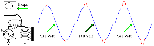
The blue portion of the waveform is the normal transformer current the red
bulge is the onset of saturation, and after that point as the voltage
increases, the resistance of the copper wire inside the transformer, is the
only further current limiting factor, because the core is saturated, and can
not accept any more magnetic fields. The more voltage applied by the
Variac
the more pronounced the effect. I won't insist you rush right out an buy a
Variac
they are rather expensive, but if you find a good deal on one, snag it,
they are very handy, and later when you acquire an oscilloscope, do this as
a lab, it not only demonstrates the principle here, but using the technique
in reverse, you can identify the voltages of various windings in a
transformer. Incidentally this technique is probably most reliable method
for doing this I have ever seen.
You can saturate portions of the core with DC, while it tries to carry
AC, in a coil that is specially designed to favor this kind of saturation.
These devices are called "Saturable Reactors" or
"Magnetic Amplifiers" Still another technique is to drive a Toroidal
core to the onset of saturation, but no further, and with two pickup coils
at 90 degrees to each other wound external of the magnetic circuit, faint
static magnetic fields can be detected, the "Flux Gate Magnetometer"
is an example of such a device, they were used in world war 2 to detect the
presents of enemy submarines.
In electronics we often use unwanted obstacles in clever ways to make
possible some new device. Often these clever exploits, are far from optimal
and require a lot of calibration, to work well though. Those of you familiar
with B H curves, may feel slighted at my bypassing something you spent months
to learn, this is intended to be a practical hands on course, that makes you
capable of designing electronic apparatii, B H curves are fine, just not all
that useful, they require core volume, and geometry, and a host of other
things to be put to practical use, and let's face it, the coils you are likely
to build, are going to be made with pre-fabricated cores, and bobbins, the
manufacturer has already done all the leg work, all you have to do is design
the coil
The next foible is a thing called core losses. Core losses for the most part
arise out of heating of the magnetic core material itself, as a result of
induced voltages, voltages that are formed by building, or collapsing,
magnetic fluxlines, crossing the conductive core material, and then those
same voltages, cause current to flow aimlessly throughout the core.
The name given these currents, is Eddy Currents so named because
they swim like Eddys in still water. When you have sustained Voltage, and
Current, you have Power, read that Heat. The design of transformers, and
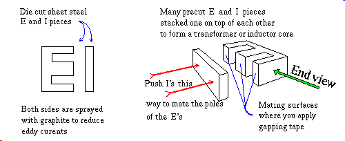
inductors, goes to heroic lengths to minimize this. Look at what they do to
60 hz AC power transformers, the magnetic core material is composed of
thin sheets of mild steel cut into "E" and "I" shapes, sprayed with
graphite, an insulator at the miniscule voltages present in the core of a
transformer, or inductor.
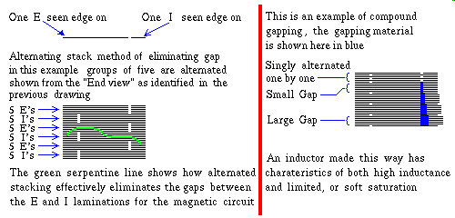
The magnetic gap is both desirable, for some things, and undesirable
for other things, a gap, that is an incomplete magnetic circuit, drastically
reduces the amount of magnetic storage, and therefore the inductance the
inductor, or transformer of a given size can hold. This is well and good
for pure balanced AC, but let there be even a small DC component in the
voltage, and the core quickly saturates, rendering the inductance,
unaccessible. Since one of the most important uses of inductors, is back EMF
a deliberate magnetic gap is introduced, to prevent complete
saturation. They even go so far as to make multi gap inductors, and
transformers, that have what amount to three or four sub-cores, that are
each gapped differently. The effect of doing this, is that you in effect
get some of the best of both worlds, good gapless performance, and if it
saturates, the other portions of the core, still have some permiance.
On the other hand, if maximizing inductance is your goal if you stack the
"E's" and "I's" alternately, in a grouped interleaved fashion, shown below,
to prevent the formation of a magnetic gap and subsequently dunk, them
into a bucket of varnish, to help hold them together, and then bake, them in
an air dry oven, you have a very good recipe for an AC transformer, I know
I used to make custom transformers.
Yet another way to achieve magnetic gap is the grind up the iron,
and sprinkle in some graphite, and a Wizard's brew of other chemicals,
bake at high temperatures, in a crucible, that forms a ceramic that has the
desired shape, "E" or "I" and presto, instant transformer core, with a very
interesting property, namely, the magnetic gap is distributed evenly
throughout the powdered iron core. Thus even a toroid eg.
shaped like a doughnut, can have a magnetic gap. These are like glass,
drop them on a hard concrete floor, and they shatter into zillions of tiny
pieces.
Back to my discussion of eddy currents another facet of core loss is
that since it is the ebb, an flow of magnetic flux lines that cause core
heating losses, the higher the frequency applied to the coil, the more
severe this problem. Using ordinary metals limits you to about 30 to 40khz
after that you get pounded by core losses. Ferrites to the rescue. Ferrites,
compounds like MnO2 Manganese Dioxide, are Semiconductor Crystals
with special magnetic properties, one of the more important ones is that
they don't conduct electricity through the core, making them ideal for
high frequency switching power supplies. To touch on this briefly, if you
can use a transformer one one-hundredth the size, very little copper wire is
required to move large quantities of power from winding to winding, thus
the wire resistance is lower, and output voltage, irregardless, of power
supply load, is more predictable. How much more predictable? In modern
switching power supply design, it is very rare, to perform a secondary
regulation of the voltage in a multiple output power supply. Translation:
If I heavily load the 12 volt output, and lightly load the 5 volt output
the servo inside the powersupply simply pumps enough energy into the
primary of the ferrite transformer to achieve regulation of one of the
outputs, the lowest one is usually selected, by a kind of analog voting
scheme, often using an LM339 integrated circuit. If it were not for this
tight magnetic coupling you would normally expect the 5 volt output to be
wildly high, maybe ten volts or so. Conversely when I load the 5 volt output
heavily, and lightly load the 12 volt output, once again the servo pumps
enough power into the primary to deliver 5 volts to the heavy load, and the
12 volt output, is astonishingly, within five percent of 12 volts.
Ferrites can be used as back EMF sources, but they saturate so completely
that in order to do this you must gap them, the smallest amount of DC will
paralyze the inductance of an un-gapped ferrite, making them an ideal choice
for a magnetic amplifiers/saturable reactors. How much gap do you need? Some
people say there is no such thing as a dumb question. Back in the 1960's I
read an account of a radio/TV repair operative who got tired of answering
the same question over, and over, "how long will this battery last in my
radio?" and one day, a fiendish idea ran through his head, there after he
always replied "three weeks, two days, fifteen hours, and three minutes"
he reported it was amazing, you'd say that, and then watch the light go on,
as they came to the understanding of the stupidity of their question.
Their facial expression, would usually undergo three distinct phases,
perplexity, anger, and lastly, Eureka. It is in the spirit of this that I
will say, the gap is between 1, and 5 one thousandths of an inch, usually
formed by layering one mil thick Kapton adhesive tape between the mating
surfaces of the pole pieces. In truth since it so easy to adjust the gap
this is found experimentally, after you have a circuit working suboptimally
you tune the gap, until you find the "sweet spot".
When you buy magnetic core components, and the plastic bobbins to wind the
coil onto, the folks that sell them to you, are very helpful, they have
data books, charts and graphs galore, but the factory rep, can give you
the simple scoop, which basically comes down to this, operating within
frequency, and power, limits for the given core material, wind a few turns
of wire onto the bobbin, and call that number of turns "Reference Turns"
depending on wire size, and available cross sectional window area of the
bobbin, 100 turns may or may not be a reasonable starting number for your
"Reference Turns" then put the core pieces around it, with some gapping tape
on the mating surfaces, to get a working inductor. Measure it's inductance
characteristics using a method that closely parallels the application you
are trying to design, that is measure either, it's back EMF, it's inductive
time constant, rate of current rise, resonant frequency in conjunction with
a known reference capacitance (see Lesson 012 for details), or what ever,
this measured inductance we will call the "Reference Inductance", once you
have that; the number of "turns of wire" required to achieve the
"Desired Inductance" can be described by the following relationship. Notice
that the geometry, things like mean radius, and coil depth are
not a consideration in the design of a coil whose core forms a complete
magnetic circuit. Even a gapped core in this sense, is considered to be a
complete magnetic circuit. If you wind a coil around a rod, that has no
magnetic closure, and wish to predict it's inductance, good luck, this is
very complex, and not very accurate, most people wind a few turns, measure,
oops too much, take five turns off, re-measure, oops need a smidgin more,
add one more turn on, re-measure, and so on. Complete magnetic circuits
are much more popular, because they are more predictable, hence the
wonderfully simple formula shown below.
-------------------------------------------
                                ___________
                              /  Desired L
Turns Req  =  Ref Turns     /  ------------
                         \/       Ref L


Note:  The industry notation for my

term "Ref L" is often called   A
                                 L

and the term "Desired L" is just   L

I state this here to avoid confusion later
when you are talking to a factory rep. on
the phone, or come in contact with it's use
in print, on a data sheet.
-------------------------------------------
It is possible to build an inductor that has a non-symmetrical saturation
threshold, by simply gluing a permanent magnet to the saturable core of the
coil. These are somewhat rare, you find them in the horizontal deflection
circuit in some computer monitors, and TV sets. The tip off that you have
one of these, is that your screwdriver blade sticks to the coil without
any power applied.
Mutual Inductance:
The trouble with making series, and parallel calculations with inductors
is that some of the stuff you are trying to calculate can on occasion
escape out of one of the inductors, to affect a nearby inductor, namely
the magnetic field. So we have a way to deal with this effect, called
mutual inductance. To begin with we need to calculate it, and to do that
we cheat, we measure it. Once measured we can use it to calculate series
and parallel inductance, that takes this stray effect into account. Ok so
it's not very useful, yet, but I'm just getting started, Mutual inductance
can also be used to get you a thing called coupling coefficient and
that gets us into the subject of loose, versus tightly coupled transformers
-------------------------------------------

To find Mutual Inductance: (M)

        La   -   Lb
M = --------------------
             4

Where:
M   = the Mutual inductance expressed in
      the same units as La and Lb
La  = Total inductance of coils L1 and L2
      with fields aiding
La  = Total inductance of coils L1 and L2
      with fields opposing


In parallel, with fields aiding:

                     1
Lt = ---------------------------------
          1                    1
      ---------      +     ---------
       L1 + M               L2 + M


In parallel, with fields opposing:

                     1
Lt = ---------------------------------
          1                    1
      ---------      +     ---------
       L1 - M               L2 - M


In series, with fields aiding:

Lt = L1 + L2 + 2M

In series, with fields opposing:

Lt = L1 + L2 - 2M


                M
K = ----------------------
           ____________
         /
       /     L1  L2
    \/

Where:
M   = the Mutual inductance
Lt  = Total inductance

L1, and
L2  = inductances of the individual coils

K   = Coupling Coefficient

-------------------------------------------
To make good use of Resonant Frequency formulas, especially to use resonance
as a means of determining inductance, you need an accurate signal generator,
fortunately you already have one, your computer's sound system, driven by a
program designed expressly for that purpose, can transform your computer
system into a high quality, function generator, and oscilloscope, but the
frequency range is limited to low audio frequencies. I give details of how
to exploit this technique, in lesson 012, however it is appropriate, here
to acquaint you with the Resonant LC Frequency formulas
-------------------------------------------

To find resonant frequency: (Fr)

                    1
Fr = -----------------------------
                   ____________
                 /
       2 Pi    /      L   C
            \/


To find Inductance: (L)

                    1
L  = -----------------------------
      /            \ 2
     |   2  Pi  Fr  |       C
      \            /


To find Capacitance: (C)

                    1
C  = -----------------------------
      /            \ 2
     |   2  Pi  Fr  |       L
      \            /


Where:
Fr = Resonant Frequency in Hertz
L  = Inductance in Henrys
C  = Capacitance in Farads
Pi = the ratio of the circumference to the
     diameter of a circle
-------------------------------------------
Your Lab Experiment:
Any electro-mechanical relay has inductance in it's coil. They don't normally
spec the inductance because the coil is used as an "electro magnet", and as
I mentioned in the Audio Lecture if the soft iron pole material moves, not
only does the inductance change, but complex interactions with work being
extracted from the system, and magnetic fields finding more or less, depending
on the direction of mechanical movement, magnetic Pole material to magnetize.
Some manufacturers of relays do publish average inductance, but this is rare.
But whither they publish it or not, the inductance is there, the Lab
Experiment, takes advantage of this, and uses this inductance to demonstrate
that practical amounts of markedly higher voltage than the power source can
deliver, are achievable with a very simple circuit. If you are new to relays
it will be instructional to insist on a relay with a clear plastic case.
This is one of those opportunities where you can "look inside the clock and
watch the gears turning" when relays actuate various metal contacts move
inside them, and you get a much better understanding of how they work by
playing with them, than any classroom could ever provide.
Note:
A note about the diode, and which end is which, the symbol for a diode
looks like an "arrow striking a target" the "arrow" is the anode, and the
"target" is the cathode. Few diodes in the real world have a diode symbol
printed on them, they're just too darn small to print the symbol on the
body of the part, so the convention is to print a band around one end of
the device, that band denotes the cathode end of the diode.
Obtaining Parts for this Lab:
Radio Shack, is a convenient source for a 9 volt relay stock number 275-005
$2.99 (the one shown is an opaque blue case) and they do have a diode kit
stock number 276-1653 $2.29 (substitute the 1N4004) if the kit lacks the
1N4003 I called out. But Radio Shack doesn't stock 2.2 uf capacitors with a
high enough working voltage, so try the electronics surplus stores first,
you'll probably get a better deal, and you might find a clear relay.
Also, Surplus stores are good about letting you test to see if the relay in
question will properly actuate on a 9 volt battery, and if you have questions
about how to hook all of this up, surplus operatives, are generaly better
informed than Radio Shack Sales Personal. If you catch a surplus store
operative on a slow day, he may show you all sorts of neat things you can do
with the relay you are purchasing. Good luck, and have fun.
The last item, in the Learn Electronics, section, is not a lesson, but a list
of places, Catalog Order, Electronic Surplus stores and the like, that can
get you started on the road to obtaining electronics on the cheap, but
catalog ordering involves minimum orders, and shipping, which are costly,
and time consuming, I urge you to get out both of your phone books, both
the white, and yellow pages, and not those advertiser sponsored phone books,
if your city provides one of those, burn it, now! It will cost you your whole
career! The good Yellow Pages, the ones I'm talking about, as a useful
resource, are the ones that show each, and every business listing, rather than
only the ones that pay to be listed. This is very important. The Bogus
phone books, omit the small Mom, and Pap, Electronic surplus stores, that are
likely to have the best deals. It stands to reason, if they have to pay extra
just to get listed, they have to pass that added cost on to customers, and
if they are in the mode of giving their customers a bad deal already, they
probably, are sponsoring other Revenue Opportunistic tactics, that
you ultimately pay for, in the form of higher prices.