Please read the copyleft link at the bottom of this page for further details, the rights given by this license are very generous. Not at all like most licenses you are probably familiar with.
However it is far enough along that if you're able to get magazine article projects working, yes most of them do have an error here or there, then you should be able to see past mistakes I've made, and get yours working. Oh and if you spot an error, and send it to me, I'll try to fix it on the site. Thank you.
This project would be prohibitively expensive, and difficult to find parts for, if I simply called out all the parts in it, and had you follow the dots to assemble it as a kit I assume you are working toward trying to become an engineer, someone who designs electronic circuits. Any such project works by spending money at a parts store, although that source is rapidly drying up for the hobbyist. This project works, for the most part from an inventory of parts collected over a long time, because I explain the relationships of parameters to each other, to facilitate making substitutions. Not only does this make possible the option of working from your own personal inventory of electronic parts, but it also makes it easier to find parts in an electronic parts store. There is, believe it or not, a professional title for someone that takes a design that a true engineer creates, and actually makes it work in the real world, we call these people, Electro-techs, or Electronic Technologists, this is the one paying position in the electronics world that is most like an electronics hobby. If you get in that position, you will find it the most enjoyable of any position in the electronics field of endeavor. I can scarcely say enough about this, yet it does take a certain kind of creative metal, not everyone is cutout for this. From an early age associations formed in the mind of such a child, of what can, and absolutely cannot, and what might be possible, are the mental precursors of such a creative electrical engineering technologist. You learn by doing, not by copying, you learn by designing your own, and then building it, and tweaking the design to get it to work optimally. It is often the tweaking that teaches you the stuff that cannot be taught in a classroom. Don't expect to digest this project as an integral whole, rather I hope that you build one subassembly at a time. That you get it working as good as you can reasonably build it, there's no test at the end, you either had a finished project that you'll be proud of for the rest of your life, or you'll tear it apart to build back up your inventory of parts again. And don't expect your first crack at it to be the best, once along time ago, a friend wanted an autolevel for a for a color organ, a type of light display, that responded with different colored light bulbs, to an audio source. If you've ever built one of these, you know one of the problems of operating them, is that the volume has to be set just right, to get an active vibrant display, 5 percent too low, and all the lights are out, most of the time, and 5 percent too high, they're all on all the time. The circuit I came up with the first time, took 23 transistors, and only had a three to one input range of volume it could autolevel. Then I started thinking this way, what if we didn't necessarily faithfully reproduce the audio, would the color organ really care? You can autolevel an audio signal by simply clipping it with a pair of diodes. But it's distorted as hell! But would a color organ care if it was distorted. So I tried it and the results were dismal. The lights no longer seemed to respond to the music. Then I thought some more, and I designed a kind of funny amplifier, one where the emitter charged up a large capacitor, and only during the times where the volume was increasing, did the amplifier have any output to speak of. The sound that you get from that amplifier was awful, but the frequency content over a period of time was not quashed like clipping diodes do, and since the collector signal was clipping, a lot, but not all of the time, regardless of the input volume, remember the capacitor that provided a path from emitter to ground, would pull current, downing the collector voltage, as if the transistor were in quiescent bias, but only on increasing volume, regardless of the average volume, the color organ although only on an intermittent basis, did see a full spectrum of the available audio frequency. This design, with some enhancement took only 3 transistors, and could autolevel with an input range of 15 to one. High notes in the music would still activate the blue lights, low notes the red ones, and while his was only a four channel unit, and not quite as demanding because the responding frequencies had a larger slice of the audio pie, mine was a six channel unit, and from separation stand point, it performed as well as his. He was heard to complain later "Why couldn't you have just come up with the new three transistor version to begin with?" What do you say to a question like that? I now introduce you to the Phillips Corollary to a phrase you will instantly recognize, Sometimes you stand on the shoulders of giants, and other times the shoulders of the giants you stand on are your own!
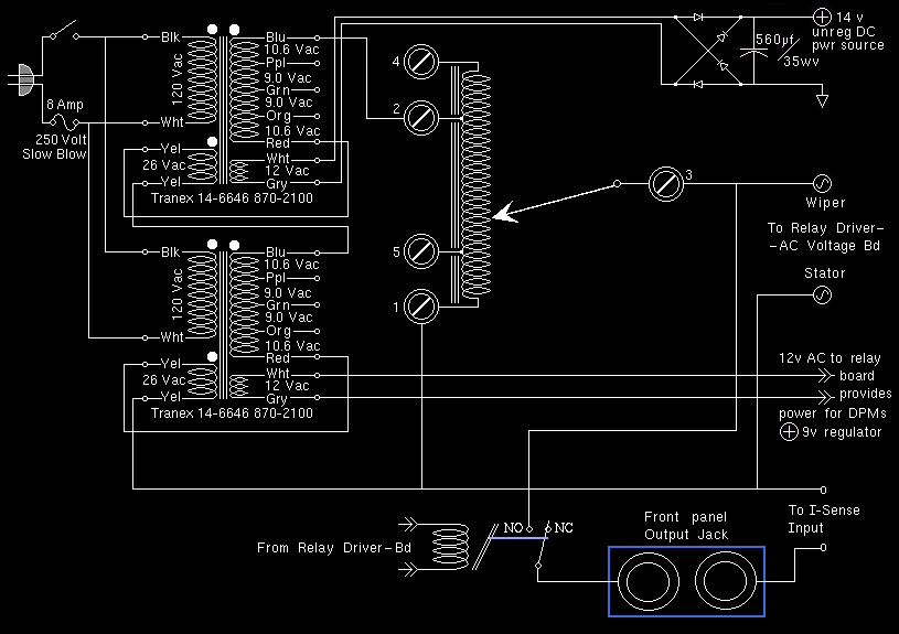
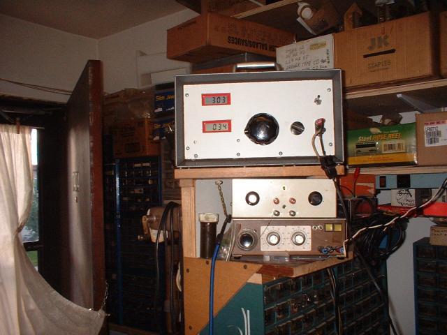
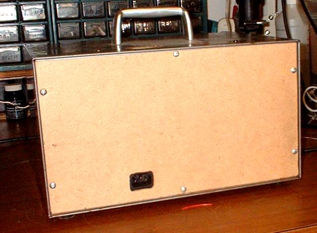
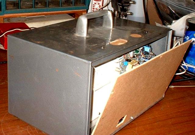
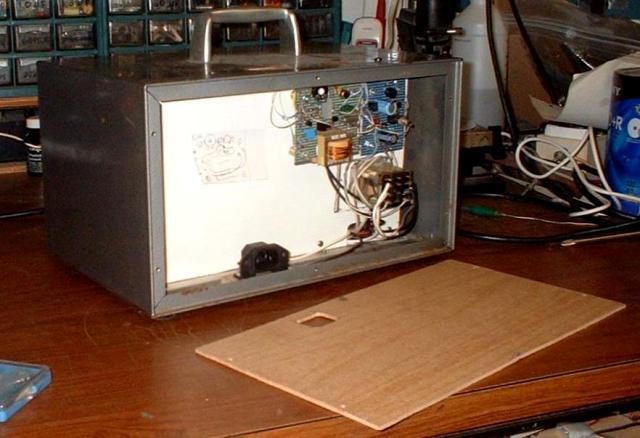
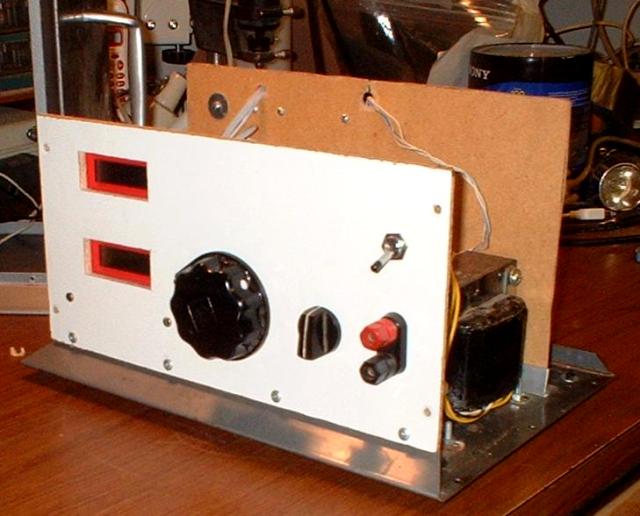
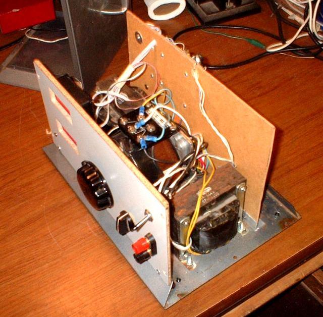
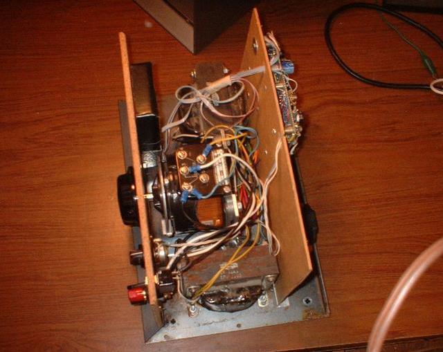
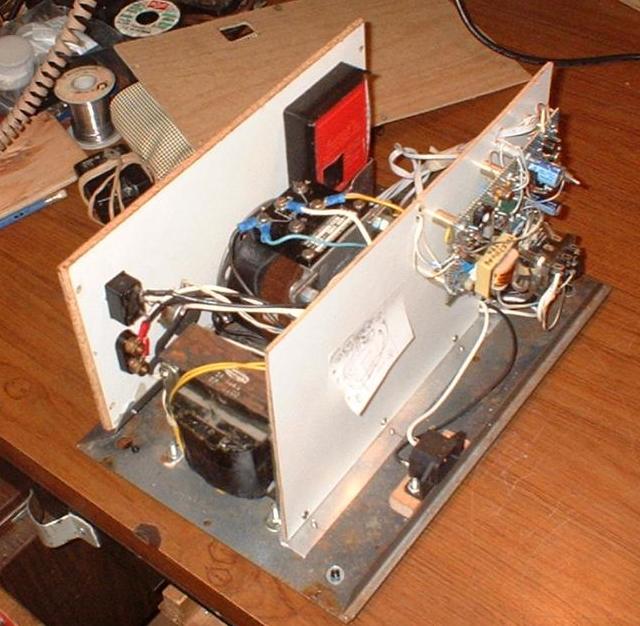
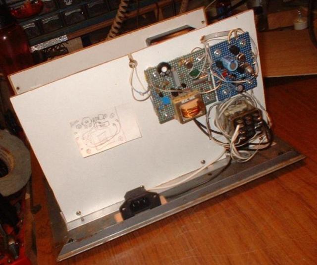
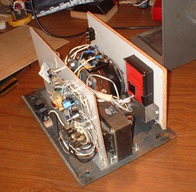
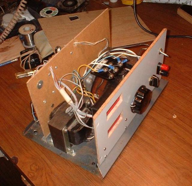
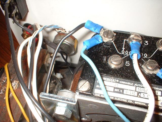
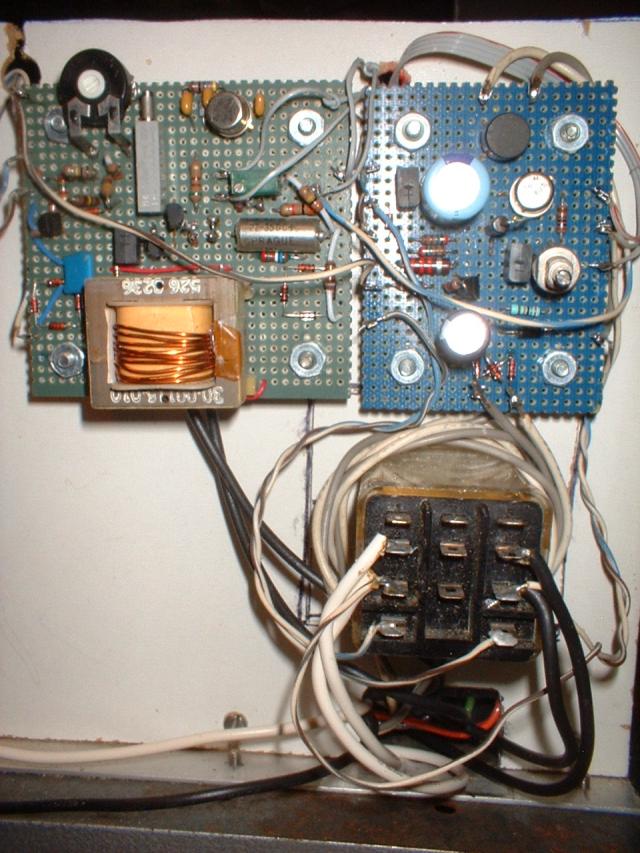
Poking around Electronic surplus stores, some advertise on line, I found an open frame variac they're often a fraction the cost of the fully enclosed type often sold with plug, cord, outlet, switch, and sometimes a circuit breaker. When you get finished with this project you will have an isolated variac, with digital output voltmeter, and ammeter, with a variable trip point self resetting circuit breaker. The advantage of an isolated output is that there is no electrical path to earth ground, meaning that if you come into contact with only one wire, you won't be electrocuted, unless the device you are testing has some path to earth ground of its own. Isolation is therefore an extra margin of safety, or being isolated can allow you to put the output in series with a some other power source, such as the 110v / 220v mains. Allowing you to boost your house current above the normal 110v or 220v. Obviously any Isolation you had is forfeited, in such a configuration. Similarly Isolation Transformers are expensive, because they are often thought of as a tool by the proprietors, also an isolation transformer is suboptimal from an aesthetic point of view. Let me elaborate, if one uses a large isolation transformer, it will occupy space inside the enclosure, forcing you to mount the variac to the right or left of it. Whereas if you had used two identical transformers, they will be, by definition the same size, and shape, and your variac can fit right between them. In other words, centered in the instrument you are designing and building. Not only is it more pleasing to look at, but the weight of the unit is evenly distributed. In my case I acquired, as one often does when buying electronic parts at bank sales, one of the more cost effective ways you can build up an inventory of electronic parts, a small lot of this one Tranex part number, which if I remember right there were two dozen of them, for $20, not bad less than a dollar apiece for 400 VA transformers, and I split the lot with someone else of similar interest, and got half of one of their lots. Anyway these particular Tranex parts if you wire all the high current secondaries in series they sum to about 55 volts AC which if you use two of them in series you get 2 X 55 = 110 VAC forming the perfect isolation transformer. The only thing that cost any real dough was the open frame variac, it was $35, and the case was $0 somebody was cleaning out their garage, and had an instrument with a volt meter, and ammeter pair, the rest was empty, so I gutted it, for the case because the case was the perfect size. Actually if truth be known I've had these sitting around for years, before it all came together in my mind's eye, and the first item to build was the dual DPM, out of two DMMs
Sometimes a variac can make a nice diagnostic tool. The idea is to start at zero volts, and slowly increase the voltage coming into the power mains of a piece of electronic gear, until things start biasing and begin to pull current. It's an old technique, in need of some modernization. The part about pull current needs some examination. Nowadays most systems are powered by burst mode switching regulators, which draw constant power from the mains of the wall socket. Notice what I said these devices draw constant power, not constant current, nor constant voltage, but constant power. Owing to the fact that burst mode switching regulators, produce a constant voltage, regulated actually, usually into something that draws an even current, given a regulated voltage, and that means that lower voltage applied at the power plug mains, translates into higher current flow into that same power plug. This runs counter to conventional wisdom, in that one assumes a resistive load, and these modern devices are anything but a resistive load, they are an active load, one that reacts to changes in input at the power mains, by lengthening the burst, if the voltage goes lower, or shortening the burst if it goes higher. All of this in an effort to produce a regulated output voltage. When the power input voltage falls below the point the system can regulate the output, one thing that can happen, depending on several factors, I'll mention in a bit, is that it can go chaotic; shifting back and forth between regulating the bursts, and non-regulating continuous RF, eg. no burst control, just steadily on, delivering full power continuously. Another word to describe this situation has been called chattering and as you might expect, the output is not only unregulated but under-shooting and dangerously over-shooting its specified output voltage. Some factors that can mitigate this behavior are, brownout protection, a flip-flop that disables the power supply if an over-voltage burst is detected, sufficiently large final filter capacitors, with time constants so long that chaotic chattering never occurs, or a soft start circuit, that is also active at the point, and some time after, the burst mode switching regulator drops out of regulation.
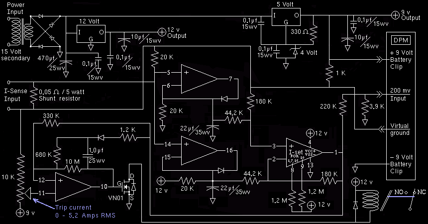
Having an electronic circuit breaker, whose trip point can be adjusted makes it possible to automatically cut the power when such a device goes chaotic. If you were to improve on my variable trip point self resetting circuit breaker, by adding an additional vernier potentiometer a kind of fine adjust to the current control knob, this functionality could be a good deal more usable. Other improvements are to add a switch to add a delay before trip that can be switched on or off, or if you were to get fancy, another potentiometer, to make it an adjustable delay. The reason such a delay is needed becomes obvious if you set the trip point to a current just a smidgen above the steady state required to light an incandescent lamp. Once the lamp is lit it will stay lit for the life of the bulb, however turn off, then back on, the power to the variac, or to the light bulb itself, and the electronic circuit breaker attempts to power up the bulb, but the inrush current required to heat a cold filament is so great that it exceeds the trip current, the circuit breaker trips, the filament cools, then the circuit breaker self resets, only to repeat the cycle over and over again forever. Another variation, is to connect both a push button, and a switch in parallel to the delay circuit, so that you can set the current very close to the trip point, and press the button to get past the inrush, thereby remaining quick to respond to a potential chaotic anomaly. As you can see there is no one right way to do this. Also much to my chagrin I found out too late that using a transformer to detect current, is not as linear as I assumed it would be. I left it for some future redesign, of the entire current subsystem, one that involves using the National Semiconductor part number LM346 a Quad Op-Amp used as precision rectifiers, not unlike the circuit below.
 In the above circuit the isolated variac output should be made to pass
through the shunt resistor on the left hand side, and through the
N.C. normally closed relay contacts on the right hand
side. The trip point is set by a potentiometer,
lower left that sets a voltage
between 0, and 3 volts to compare to the output
from the Precision Rectifier such that given an input current
of 5 amps RMS, the final summing amplifier will deliver
2.8796 volts, nearly the max voltage the potentiometer can reach,
but the devil in the details is the effect of the hysteresis circuit.
In the above circuit the isolated variac output should be made to pass
through the shunt resistor on the left hand side, and through the
N.C. normally closed relay contacts on the right hand
side. The trip point is set by a potentiometer,
lower left that sets a voltage
between 0, and 3 volts to compare to the output
from the Precision Rectifier such that given an input current
of 5 amps RMS, the final summing amplifier will deliver
2.8796 volts, nearly the max voltage the potentiometer can reach,
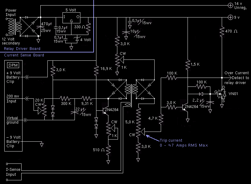
but the devil in the details is the effect of the hysteresis circuit.The math is a little messy, but if you're curious, the Precision Rectifier converts an RMS AC sine wave to its Peak-to-Peak, eg. times 2, value, multiplied by a DC voltage gain of 4.0724 inherent in the choice of gain limiting voltage divider resistors 44.2 k ohms, and 180 k ohms, for a total AC RMS to DC voltage gain of 8.1448
Plug in 5 Amp times 0.05 ohm, times Square root of two, RMS correction factor, times 4.0724 gain limiter then we double that value Precision-Rect reads peak-peak and you get 2.8796 volts DC which represents the full scale current the variac is rated for, at the output of the precision rectifier.
Applying the variac rated max RMS current to the shunt resistor the positive input of the trip point comparator before it trips, is only 2.624 volts due to the hysteresis circuit, the 330 K ohm, and the 10 meg ohm positive feedback circuit. If you divide 2.624 volts by 3.0 volts the DPM internal voltage reference, you get 0.87468 or 87% of the potentiometer dial is the trip point for a 5 amp RMS input. So with the dial turned all the way up, it trips at 5.2090 amperes RMS
Note: I show my work here, if you look at the html comment in source view of this page, short cuts and assumptions I had to make, made this far too arduous to explain, so I chose to include some of my work in the comments, and yes this whole site has such comments strewn throughout the html pages.
The 220 k ohm, 3.9 k ohm attenuator between the precision rectifiers output, and the input of the DPM, multiplies this output by 0.01742 giving a full rated current reading of 2.8796 x 0.01741849 = 0.05015864 so the display reads 05.01 if you AC couple the left decimal point to virtual ground.
The hysteresis circuit is a positive feedback circuit, with a delay to insure that once it is triggered, it won't reset for about a second. You can of course change it if you think that's too long but there's a lot to consider about this circuit, for instance the auto reset is over 160 times as fast getting the 1.0uf capacitor charged back to its former voltage, and this job has to be finished before the relay closes again. Most relays take 30 milliseconds to do so, but it's one of the many things you need to consider. Remember the HTML source is your friend if you want even more detail. But an inrush current delay to allow current to stabilize before the trip mechanism begins to assert control is another matter entirely. How do you do this? There are many ways, consider what happens, if your delay completely blocks the function of the electronic circuit breaker for say, 50 ms. If you applied a zillion amps it would take 50 ms regardless, before it broke the circuit, even a slow blow fuse will blow instantly if you apply a zillion amps to it, hell apply a zillion amps to any fuse and it will go its separate ways, as in, it will explode, leaving no trace of itself. So since there is no one right way to do this, and especially since I make no claim this thing will actually work, remember this is just an idea of how to improve on my current transformer version of the whole current sense subsystem, I've never built one yet, I'm not saying this thing will even work, there isn't even one prototype, so yours assuming you build one, might very well be the first. Sometimes I doodle on paper, and then completely scrap the whole thing.
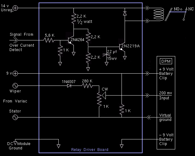
This whole system derives its reference from the DPM's virtual ground, which is an open collector output that provides a regulated minus 3 volt sink into the battery's negative terminal, and referenced from the + 9 volt battery terminal. To use this up-side-down regulator, as a positive regulator, you must provide a pull up resistor, and take care not to exceed current that resistor can pull. That's why I placed a 1 k ohm resistor between virtual ground, and the plus 9 volt rail. If you do the math, there is approximately + 6 volts between ground and virtual ground, and another + 6 volts between virtual ground and + 12 volts, it is as if virtual ground is a center tap of the regulated 12 volt supply. It doesn't just work out that way, it is by design. Also; and this is very important, the ground, + 9 volt rail, and the + 12 volt rail are common only to this circuit, do not use these for other subsystems of the variac project. The virtual ground (or + 6 ref), can, at most, source what the 1 k ohm can pull, a mere 3 ma making it useful only as a reference voltage, and it is common with the variac or the front panel output terminals / binding posts.
A peak to peak reading AC ammeter calibrated for RMS conversion is really only valid for resistive loads. As long as you know this, and can correct for it, life is good. Another approach is to simply ignore the resistive load world, and assume a conversion for everything, by calibrating it for peak to peak AC amperes.
This kind of thing is so wide spread, that even multimeters read AC voltage in average half wave and are calibrated in RMS, which is even worse. There are two types of meters that do read true RMS, the first type are prohibitively expensive, and technologically very old, they employ a kind of high vacuum tube to insure air molecules don't pull heat away from the RMS converter, which is a four strand metallic spider web suspension system, holding a resistive heating element that is welded to a thermocouple of two dissimilar metals barely large enough to see with the unaided eye. It works by sensing the heat given off by resistive heating element powered by an arbitrary waveform to heat it. Such instruments are slow to respond, delicate, insensitive, and the operating voltage is so close to the voltage that will de-calibrate it, or out right burn it out, that most of them meet such a fate in the hands of an unseasoned technician. The second type uses a precision rectifier circuit to control current charging a capacitor to integrate over time, both the upper half, and the lower half of the wave separately to arrive at a true RMS reading. Needless to say, the frequency response of such a meter is so bad that it makes the jobs you often need such a meter for, seldom very useful. At least with true Peak-to-Peak, you know that what you're reading actually means something, assuming you do know something about the load you're dealing with. The rational I used goes like this, first the power source is alternating current that is sinusoidal, second most of the time, you're either driving a resistive load, trying to compare current at one voltage, to current at another, so it don't matter, and third, it's simple to change the calibration, you change one resistor, in the attenuator between the precision rectifier, and the DPM. Now you have your choice, RMS, peak to peak, or simply peak.
A DMM (Digital Multi Meter) by any good reasoning should be more expensive than a comparable DPM (Digital Panel Meter) simply because they've got everything the panel-meter has parts wise plus at the very least banana plugs-n-probes, the big range selector knob, However the market scale dynamics are such that China can sell many more multi-meters, of a given model to the US public than they could ever hope to sell panel-meters to that same market. As a result panel-meters are by comparison quite rare, and seldom inexpensive. Whereas DMMs are often loss-leader items, priced to draw people into the store.
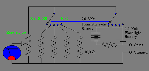
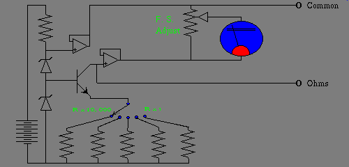
If you were to goto lesson 017 Diode Approximations about a third of the way down the page, you find this diagram.
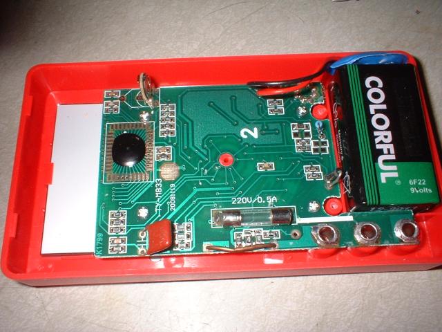
The above photo is the DMM with the back removed, if you are considering converting a DMM of this exact model, I would caution you not to put too much faith in the model number, I saw several on the hang-tack in the store, that looked identical, the only things that differed were the model number, and the packaging, such is the world of mass marketed loss leader instrumentation. Not that I would ignore the model number totally, but look at the pictures and compare them to yours before you decide. Electrically speaking these things aren't too much different from one another anyway, so even if yours is quite a bit different in appearance, if you think my instruction is good enough to risk experimenting on a two dollar loss leader DMM, give it a go.
Most of the time what you want is that high input impedance 200 Mv digital meter. Get out a paper pad and pencil, and maybe even a straight edge. If you turn the knob to the DC volts section and then to the 200 Mv subsection, and then slowly, and carefully, disassemble, it in such a way that you preserve the information of what contacts in that multi-position range selector switch are mated against which copper circuit foils, you can now write it all down. Next you study what traces are part of the 200 Mv meter circuit, and which are not. You should be able to power it up, as a 200 Mv meter, and that test also verifies you haven't made any mistakes along the way. Caution do not use the battery that powers the meter as a test voltage. These meters have virtual grounds, and must be isolated from their own power source. Failure to pay attention to this can damage the Virtual Ground. In my case there's a convenient hole that fits the threads of a #7 sheet metal screw in the back of the knob, and a similar hole that fits the body of such a screw. If you were to use that hole to partially reassemble the knob, and its beryllium-copper springy electrical contacts that mate with the circuit foils, this may serve as a technique to help you to reverse engineer the range selector switch. I did not go this route, but I was tempted to. The goal here is to figure out where exactly the board can be cut, and still have a working 200 Mv meter-head, and to figure out where to connect the off-board wires, and any jumpers that are needed to complete all the circuits in this cutoff variant of the meter, that the knob, its beryllium-copper contacts that mated with the circuit foils, and copper circuit traces, all of which will be gone after you slice off the bulk of circuit board, that's unnecessary to make a 200 Mv meter-head for a DPM.
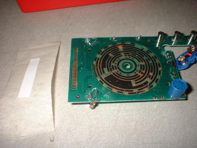
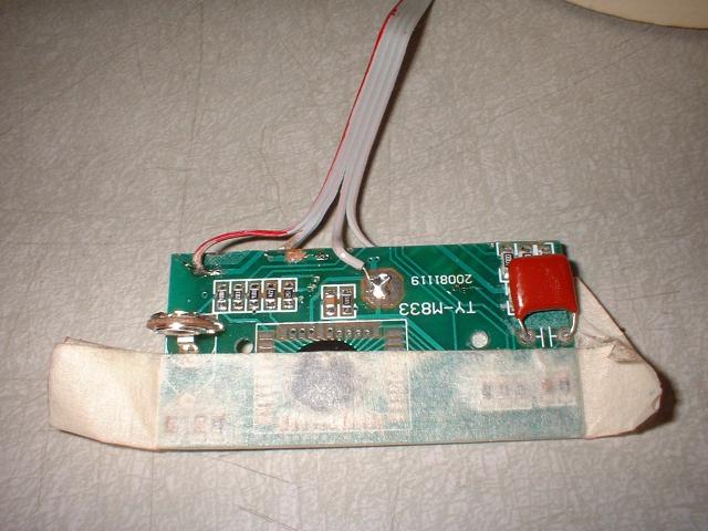
The above photo shows the clean copper fingers that touch the LCD caterpillar tape be careful not to touch either the LCD or the caterpillar tape neither shown here, or the copper fingers on the circuit board with your bare hands, oils and other debris on your skin, even the skin itself, the cells peel off, and can add to contamination. Here on the left I make a kind of bandage a strip of non-sticky paper stuck near-center to a strip of masking tape, to protect the fingers, while I work on it.
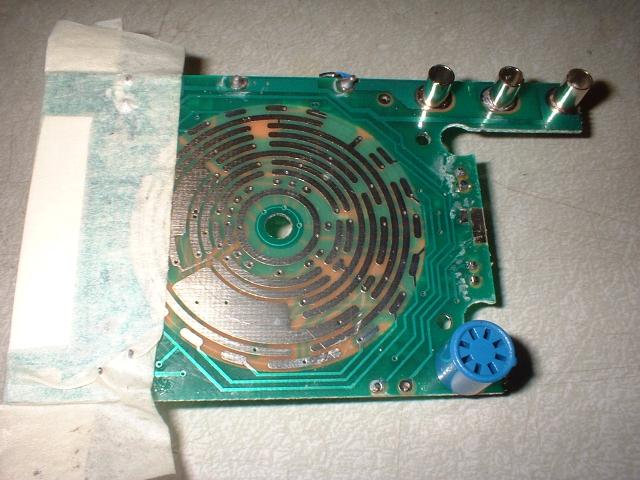
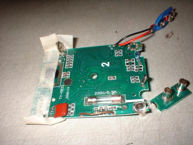
In the above photo the on the left edge, the display fingers are covered with a protective layer of non-sticky paper, held in place by overlapping masking tape. Notice the three tubular electrical contacts that form the female Banana Jacks for the meter leads to plug into, in the upper right hand corner of this photo. Later when I use the Dremel Drill Press to cut the circuit board, this protrusion with the three tubular banana jack contacts, would make the cutting operation awkward, and difficult, so...
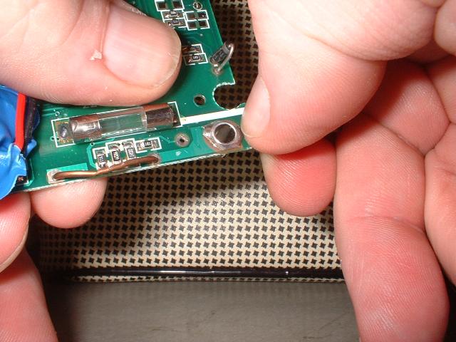
...I simply break them off.
I considered breaking off the blue transistor test socket, however it didn't seem to pose that much of a problem, so I left it alone.
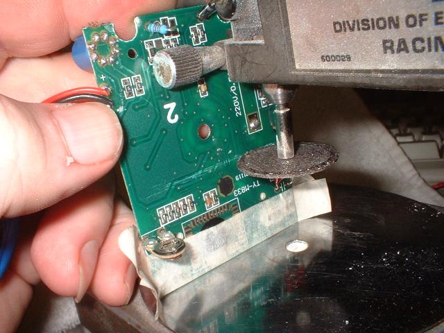
Doing the cut:
I used a Dremel drill press with a fiber cutoff wheel to gently cut the circuit board. With the wheel spinning at about 4000 RPM (+/- 1500 RPM) and sliding the circuit board through the cutting area, with minimal pressure, taking off a little at a time doing many many passes, the board gets ever thinner, until only a paper thin membrane is all that's left where the cutoff wheel has been cutting. It's almost impossible to get it that thin and not punch through here and there, but you should try. At some point, near half way through, one should flip the board over and cut from the other side. In my case I avoided completing the cut at one end, I left a three eights of an inch of the board intact, to allow handling, and taking pictures, before finishing the cut. This process runs the risk of building up static electricity, that damages the circuit beneath the epoxy blob. The only practical thing I can suggest is to boil some water if the air is particularly dry to help reduce this risk. All I can say is that modern parts are diode protected better nowadays, so the risk isn't what it once was. Just be careful your body can carry a charge different from everything around you, touch metal surfaces with your finger to discharge voltages differences, before you allow this circuit board to come into contact with them, that way you'll minimize the charge difference your hand will couple into sensitive inputs on the circuit board.
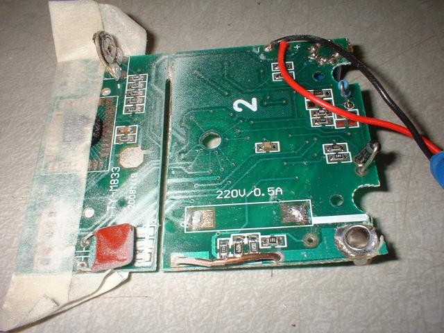
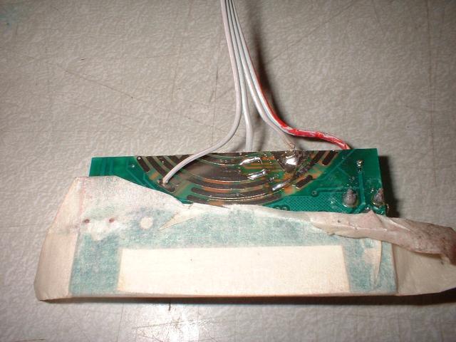
The above photo serves as a nice example of where to make the cut, also when studying the off board wiring, and where the jumpers go, it can help verify how the original circut was wired, especially how signals passed through the range selector switch.
Study these photos, the via holes are large enough to fully accommodate the stranded conductors in ribbon cable. Once soldered these wires are more fragile that you probably expect, the solder wicks up in under the vinyl insulating jacket, which acts like a lever, small amounts mechanical flexing of the cable are coupled right to the point where the wire enters the hole, and because of the wicking effect, the stranded wire acts like a solid wire, fatigues right at that point, and breaks off. As soon as it's convenient, like when the case is mounted back on, you should devise some strain relief to fasten the cable down to the case. Also soldering these wires to circuit traces is untenable. Instead if you solder a wire to an unused via hole, and on the other side of the board, wrap a turn or two of wire-wrap wire, to the protruding ribbon cable stranded wire to anchor it down, now soldering the wire wrap wire to circuit traces is a whole lot easier, for one thing they tend to stay put once bent into place, while you solder them to a circuit trace.
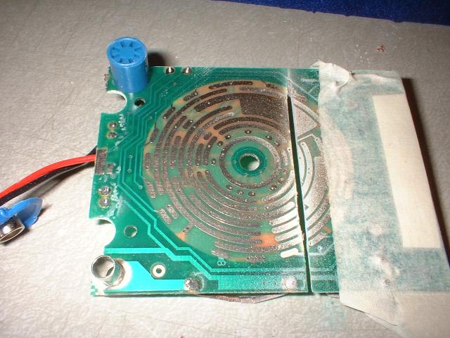
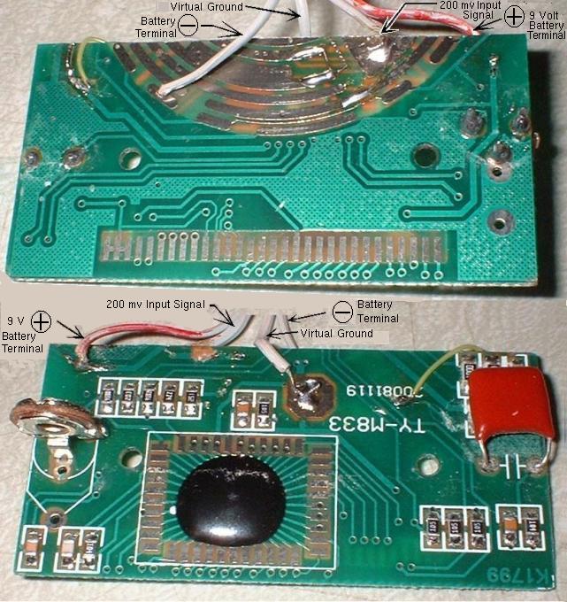
The purpose of the next photo is to show the Signal Names of the off board wires. Notice I've gone to some effort to insure the order of signals within the four wire ribbon cable makes some kind of sense. We think, or at least many in the field think of the wire carrying the return path that completes the circuit of a named current or signal, as a kind of Electrical Ground. In a similar vain, absent excluding factors like high frequency crosstalk between adjacent conductors on the cable where exceptions must be made. Tradition dictates that signals, and power busses begin labeling with the highest to the lowest, negative voltage at one end, usually the left end, proceeding through to ground, continuing on to the lowest positive voltage, through ending with the highest positive voltage at the other end, usually the right end, common in a system, or module. Like rules governing prose, you can't follow them all, these are merely guidelines to make things neater, and more readily understood.
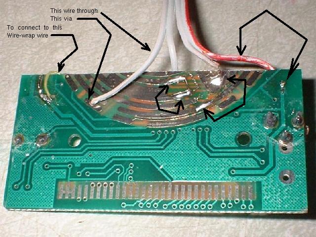
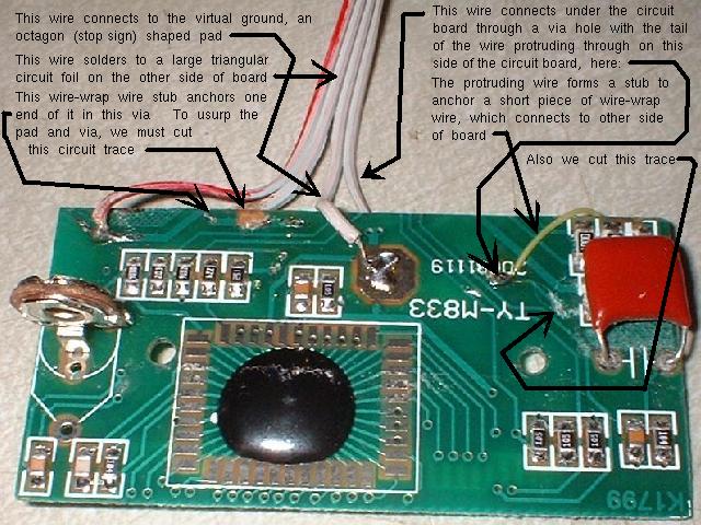
The above photos show how I jumpered some of the range selector contact pads together, and how other traces were cut to isolate large pads and vias to make available soldered anchors for off board wiring, that otherwise wouldn't be. Soldering a 26 awg wire to a to a trace that's only a 100th of an inch wide is impractical to say the least, let's say you actually did manage to get the wire firmly soldered to it, the epoxy bonding agent that attaches the copper trace to the epoxy-glass base board will very likely be compromised by heat. Furthermore, the vinyl jacketed copper wire, that began life as a piece of very flexible stranded 26 awg wire, is now a hunk of lead/tin/copper, or you can substitute the more politically correct eutectic alloy of your choice, but regardless what alloy you choose it still amounts to a solid core 24 awg jacketed wire cantilevering this delicate strip of heat compromised epoxy bonding agent a mere 100th of an inch wide! In simple layperson speak, "It'll break right off" follow this by an expletive for full effect, and you have the quintessential sound bite.
DPM summery:
As I said before, even if your DMM circuit is laid out different, the concept is still the same, set the range selector switch to the most sensitive DC range and reverse engineer the paths from the input jacks, through that switch, to the epoxy blob, and from the battery clip through its switch to power the epoxy blob. Finally to figure out where the virtual ground is, and how to stiffen its output, if necessary, as I did, using the resistance range or diode check range, for a hint as to how much current you can pull, source/sink from the virtual ground. This is easily done if you haven't yet started cutting the DMM, simply switch it on, set the range to a setting that will pull some current, hopefully the highest current, and with a second meter simply measure the current. Then I would first tack-solder enough wires to make it work as a DPM. This will allow you to determine where you can cut the board. Usually the cut is very close to the blob, and the LCD display. Making your DPM nicely small. Next you cut the case, the half that houses the board, and display, and assemble that part with the off board wiring. Last is the back, when I came to this juncture, I snapped one DPM, the one I was using as an AC volt meter into the top half of the back, and there was enough room left to also mount the second DPM, identically wired as the first, into the bottom, making a nice subassembly with two DPMs into the same unit. The second DPM was to be used as a digital ammeter. The thing that determines what units they are, Amps or Volts is the signal conditioning. The next order of business.
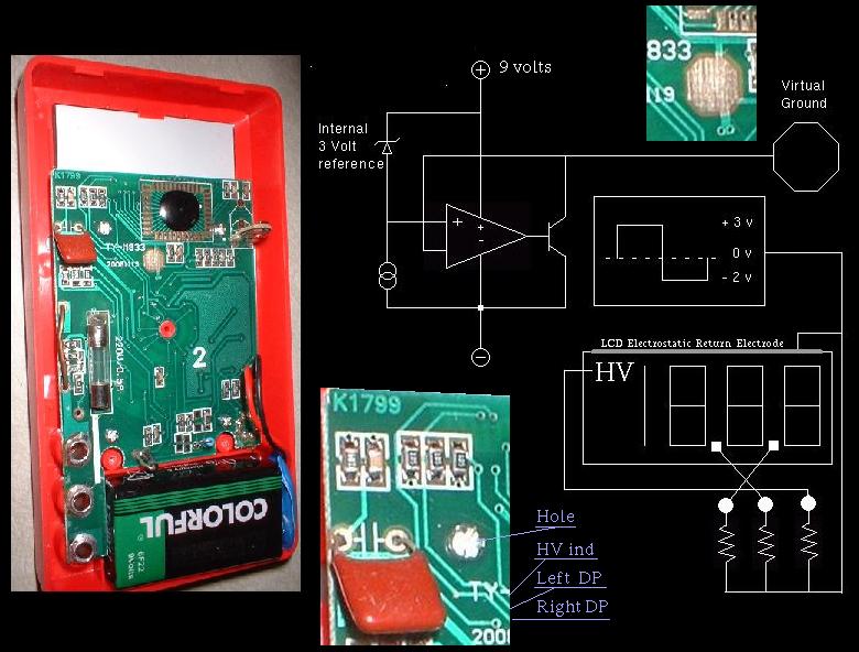
The above photo is the DPM with a previously discussed Virtual Ground where I discuss its use. I also gave a few guide lines on figuring out how much current this virtual ground will safely sink.
One other thing you need to know, is that LCD display elements require near perfectly balanced AC to activate the delicate digit segments. The slightest imbalance, even one percent, will present enough DC to electroplate the material off the electrode, and into solution, never to work again!. The solution is simple enough though, AC couple the signal by placing a DC blocking capacitor between the LCD element, and some AC ground. I found that a 0.033 microfarad capacitor connected between the LCD element and the virtual ground would fully activate the display, without any noticeable dimness, I then doubled the value to 0.068 microfarad just to be on the safe side. But don't take my figures, although they'll probably work, do your own experimentation.
The Battery (-) Terminal is thought of as a ground return for the subsystem powering the DPM, it is the counter part to the (+) 9 Volt Battery Terminal normally a 9 volt transistor radio battery, convenient, and most important ISOLATED! I get around the isolation requirement by using the virtual ground as a reference voltage fed back into my circuits that condition AC voltage, and current, into the zero to 200 mv DC DPM input signal. In the speculative LM346 based precision rectifier, a tentative replacement circuit for the existing current sense transformer based Digital Ammeter, and variable circuit breaker subsystem, I show rather extensive use of this concept.
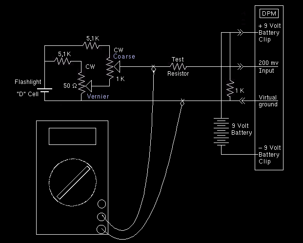
However for a simple test procedure, connecting a simple 9 volt transistor radio battery (+) and (-) power supply terminals to the proper wires of the ribbon cable, can't be beat for simplicity. All the while being careful to position the off board wires, here are four of them, so as to prevent shorting any of them to anything they shouldn't touch will power up the DPM. Depending on whither you left in the last resistor in range selector switch, you may have removed the bleeder resistor. If some random voltage is flashed on the display, or the most significant digit is a one with the others blank, with or without the sign on or off, (indicating a +/- Over Voltage) is likely due to some residual charge on a capacitor internal to the DPM circuit. If momentarily shorting the 200 mv input to the virtual ground zeros the display, the bleeder resistor is probably gone, so the input impedance is so high that the otherwise insignificant capacitor, is now sporting a time constant in the tens of minutes. To fix this, place a 100 K ohm to 10 megohm resistor across the 200 mv input, and virtual ground.
From the standpoint of this project, the ultra high impedance these meters exhibit is of little use, the ammeter is driven by a 20 K ohm calibration potentiometer, the voltmeter is even less so, with a 1 k ohm calibrator.
There are three diagrams, each one details an electronic subassembly
1. The main isolation transformer, and Variac.
2. Current sense, Digital Ammeter, and variable circuit breaker schematic.
3. Relay driver, Digital Voltmeter calibrator.
Interconnection between these three subassemblies should be obvious, just follow the signal labels.